B
ENGINE
Retighten
the
securing screws. and
withdraw
the
timing plunger. This
procedure
should be
repeated
for
the
centre
cylinder (Red and Black lead).
Remove the
aUto
advance unit centre bolt, and
remove
the
oYerslze washer. Care should
be
taken
to
ensure
that
the
auto advance unit
is
not
released. Retighten
the
bolt.
The spark timing wlll now
be
correct
on
all
cylind ers
Remove
the
timing piunger and body, and replace
the
blanking plug and fibre washer. Refit
the
sparking
plugs and rocker covers, and engage
neutral
position
on
the
gear lever.
SECTION
827
IGNITION
TIMING
USING
A STROBOSCOPE
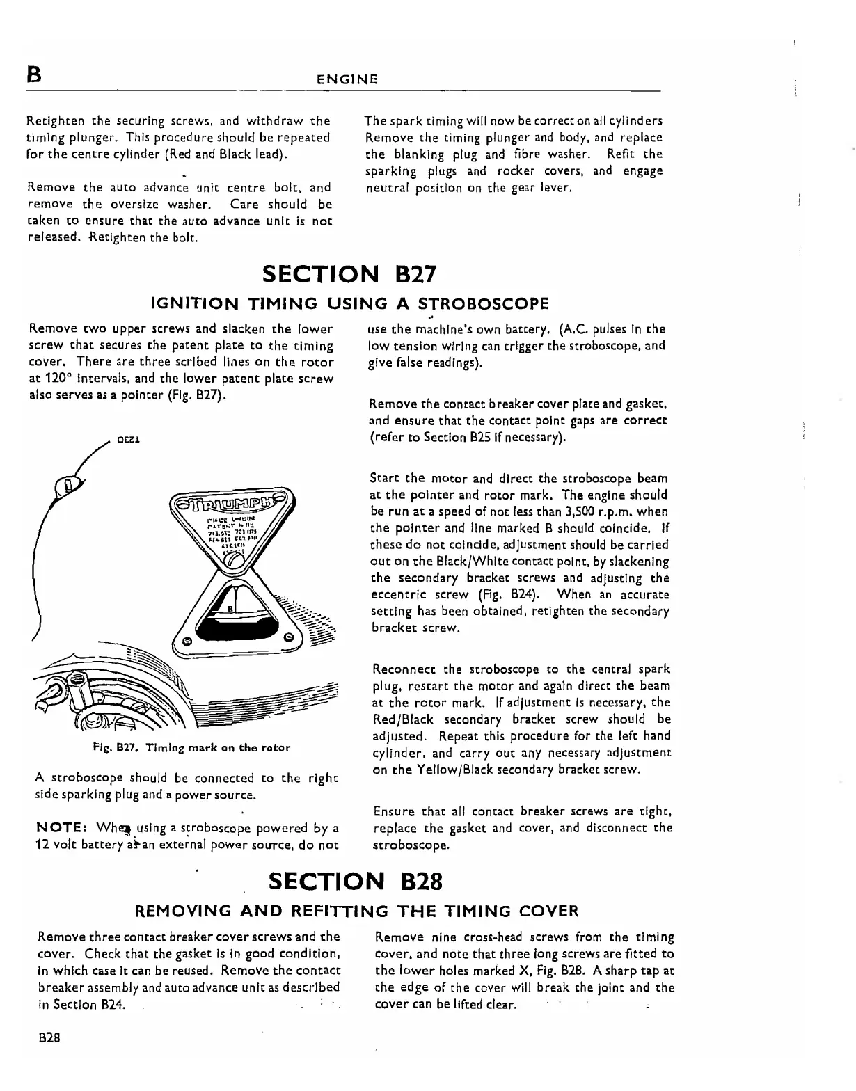
Remove
tWO
upper
screws
and
slacken
the lower
screw
that
secures
the
patent
plate
to
the
timing
cover.
There are three scribed lines
on
the
rotor
at
120" intervals, and
the
lower
patent
plate
screw
also serves as a
pointer
(Fig,
B27).
O£~i
Fig.
B27.
Timing mark on
the
rotor
A
stroboscope
should be connected
to
the
right
side sparking plug and a
power
source,
NOTE:
Wh,,!.using
a
s~roboscope
powered
by a
12
volt
battery
a~an
external
power
SOUTce.
do
not
"
use
the
machine's own battery, (A,C. pulses
in
the
low
tenston
Wiring
can
trigger the stroboscope, and
give false readings),
Remove
the
contact breaker cover plate
and
gasket.
and
ensure
that
the
contact point gaps are
correct
(refer
to
Section
B2S
If
necessary).
Start
the
motor
and
direct the stroboscope beam
at
the
pointer
and
rotor
mark, The engine should
be
rUn
at
a speed
of
not less than 3,500 r.p,m.
when
the
pointer
and line marked B should coincide.
If
these
do
not
coincide, adjustment should be carried
out
on
the
Black/White contact point,
by
slackening
the
secondary
bracket screws and adjusting
the
eccentric
screw
(Fig,
B24),
When
an
accurate
setting
has been obtained, retighten the secondary
bracket
screw.
Reconnect
the stroboscope to the central spark
plug,
reStart
the
motor
and again direct
the
beam
at
the
rotor
mark,
If
adjustment
is
necessary,
the
Red/Black secondary bracket screw should be
adjusted.
Repeat this procedure for
the
left hand
cylinder,
and
carry
OUt
any necessary
adjustment
on
the
Yellow/Black secondary bracket screW.
Ensure that
all
contact breaker screws are tight,
replace
the
gasket
and
cover,
and
disconnect
the
stroboscope.
SECTION
828
REMOVING
AND
REFITTING
THE
TIMING
COVER
Remove
three
contact breaker
cover
screws
and
the
cover. Check
that
the
gasket
is
In
good
condition,
in
which case it can
be
reused, Remove
the
contact
breaker assembly
and
aUto
advance unit
as
described
in
Section
B24.
B28
Remove
nine cross·head screws from
the
timing
cover,
and
note
that three long screws are fitted
to
the
lower
holes marked X,
Fig.
B28,
A
sharp
tap
at
the
edge
of
the
cover
will
break
the
joint and
the
cover
can be lifted clear.