ELECTRICAL
SYSTEM
SECTION
H15
WARNING
LAMPS
H
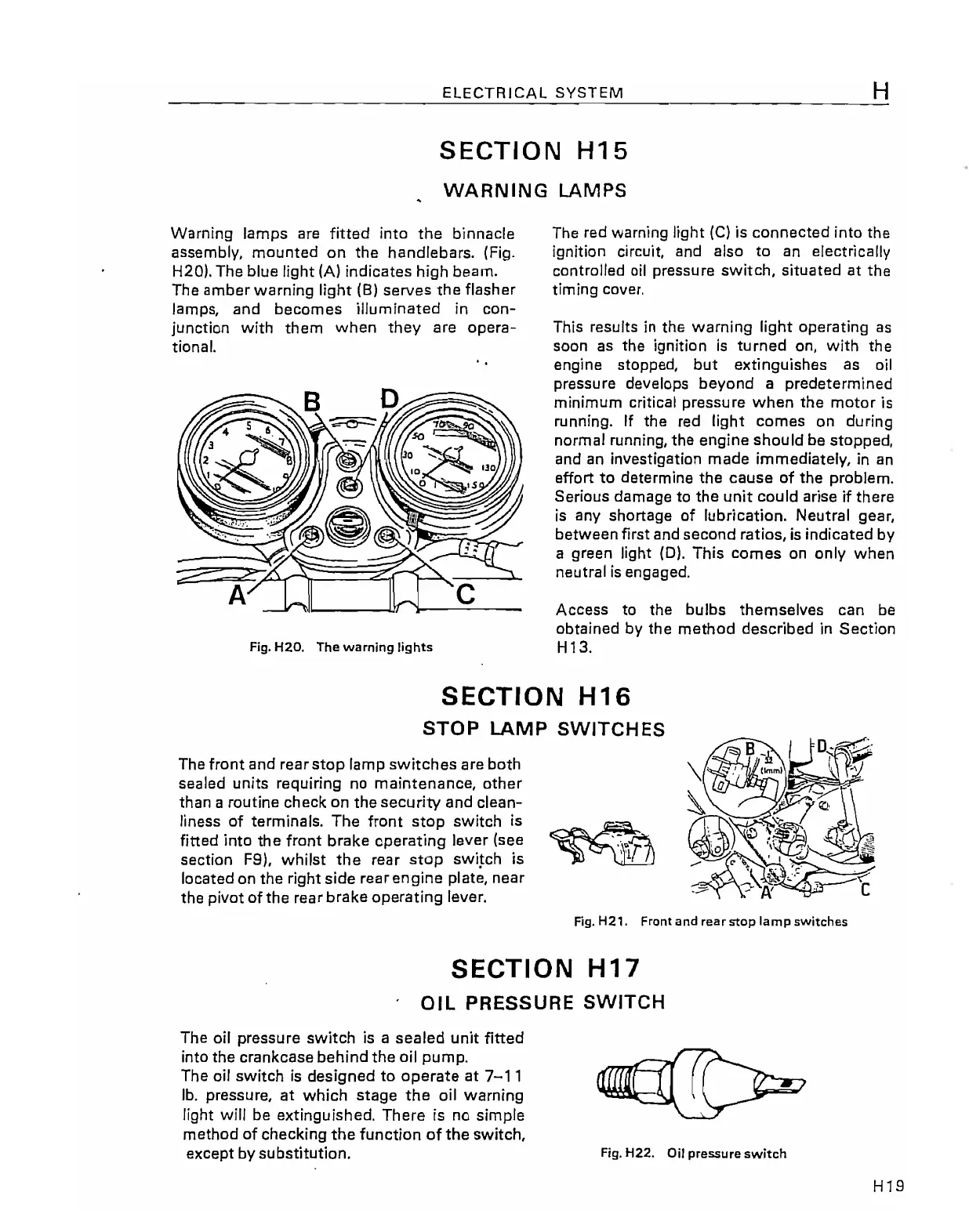
Warning lamps are fitted into
the
binnacle
assembly,
mounted
on
the
handlebars.
(Fig.
H20). The blue light
(A)
indicates high beam.
The
amber
warning light (8)
serves
the
flasher
lamps,
and
becomes
illuminated
in
con-
junction with
them
when
they
are
opera-
tional.
..
Fig.
H20.
The warning lights
The red warning light
(C)
is
connected
into the
ignition circuit, and also to an electrically
controlled
oil
pressure
switch,
situated
at
the
timing cover.
This results
in
the warning light operating as
soon
as
the ignition
is
turned
on, with
the
engine stopped,
but
extinguishes
as
oil
pressure develops
beyond
a predetermined
minimum critical
pressure
when
the
motor
is
running. If
the
red light
comes
on during
normal running,
the
engine
should
be stopped,
and an investigation
made
immediately,
in
an
effort
to
determine
the
cause
of
the
problem.
Serious
damage
to
the
unit could arise
if
there
is
any shortage of lubrication. Neutral gear,
between
first and
second
ratios,
is
indicated by
a green light
(D).
This
comes
on only
when
neutral
is
engaged.
Access
to the bulbs
themselves
can
be
obtained by
the
method
described
in
Section
H13.
SECTION
H16
STOP
LAMP SWITCHES
The front
and
rear
stop
lamp
switches
are
both
sealed units requiring no
maintenance,
other
than a routine check
on
the
security
and
clean-
liness of terminals.
The
front
stop
switch is
~
fitted into
th)
e front
brhake
operating
lev?r
(s~e
'\,r
section
F9,
whilst t e rear
stop
sWIFch
IS
located on
the
right
side
rear
engine
plate,
near
the pivot
of
the
rear
brake
operating
lever.
Fig.
HZ'.
Front and rear stop
lamp
switches
SECTION
H17
OIL
PRESSURE
SWITCH
The oil pressure switch
is
a
sealed
unit fitted
into the
crankcase
behind
the
oil
pump.
The
oil
switch
is
designed
to
operate
at
7-11
lb.
pressure,
at
which
stage
the
oil warning
light will be extinguished.
There
is no simple
method
of checking
the
function
of
the
switch,
except by substitution.
Fig.
H22. Oil pressure switch
H19