H
ELECTRICAL SYSTEM
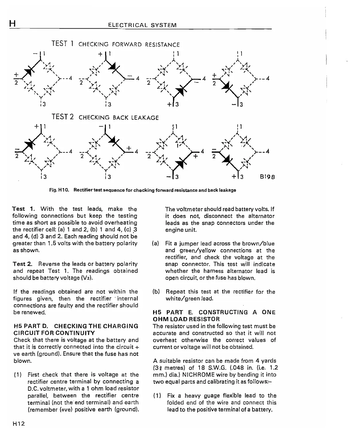
TEST
1 CHECKING FORWARD RESISTANCE
TEST
2 CHECKING BACK
LEAKAGE
-~
,
, ,
,,-
"c
..
"'~'
+
---(
4
2
\.1/
,./
..e-;ol<..
~-¥
/,
>'1'
, , ,
y
13
Fig. H 1
O.
Reetifiertest sequence
for
checking forward resistance and back leakage
Test
1. With
the
test
leads, make
the
following connections
but
keep
the
testing
time
as
short
as
possible to avoid
overheating
the
rectifier cell:
(a)
1 and 2,
(b)
1
and
4, (c) 3
and
4,
(d)
3
and
2. Each reading should
not
be
greater
than
1.5 volts with
the
battery
polarity
as
shown.
Test
2. Reverse the leads
or
battery polarity
and
repeat
Test
1.
The readings
obtained
should be battery voltage
(V2).
If
the
readings obtained are
not
within
the
figures given, then the
rectifier'
internal
connections are faulty and
the
rectifier
should
be renewed.
H5
PART
D.
CHECKING
THE
CHARGING
CiRCUIT
FOR
CONTINUITY
Check
that
there
is
voltage
at
the
battery
and
that
it
is
correctly
connected
into
the
circuit +
ve earth (ground). Ensure
that
the
fuse
has
not
blown.
(1) First check
that
there is voltage
at
the
rectifier
centre
terminal by
connecting
a
D.C.
voltmeter, with a 1
ohm
load
resistor
parallel,
between
the
rectifier
centre
terminal (not the end terminal)
and
earth
(remember
(+ve)
positive
earth
(ground).
H12
The
voltmeter
should read battery volts.
If
it
does
not, disconnect the
alternator
leads
as
the
snap
connectors
under
the
engine
unit.
(a)
Fit
a
jumper
lead across the
brown/blue
and
green/yellow
connections
at
the
rectifier, and check
the
voltage
at
the
snap
connector. This
test
will
indicate
whether
the
harness alternator lead
is
open
circuit,
orthe
fuse has blown.
(b)
Repeat
this
test
at the rectifier for
the
white/green
lead.
H5
PART
E.
CONSTRUCTING A
ONE
OHM
LOAD RESISTOR
The
resistor
used
in
the following
test
must
be
accurate
and
constructed so that it will
not
overheat
otherwise the correct values of
current
or
voltage
will
not
be
obtained.
A suitable resistor can be made from 4
yards
(3
~
metres) of
18
S.w.G. (.048
in.
(i.e.
1.2
mm.) dia.) NICHROME wire
by
bending
it
into
two
equal
parts
and calibrating
it
as follows:-
(1)
Fix
a heavy guage flexible lead
to
the
folded
end
of
the
wire and
connect
this
lead
to
the
positive terminal of a battery.