PRIMARY DRIVE
SECTION
C9
PRIMARY
CHAIN
SPROCKET
ALIGNMENT
c
It
Is
essential
that
the
primary chain misalignment
does
not
exceed
0.010
In.
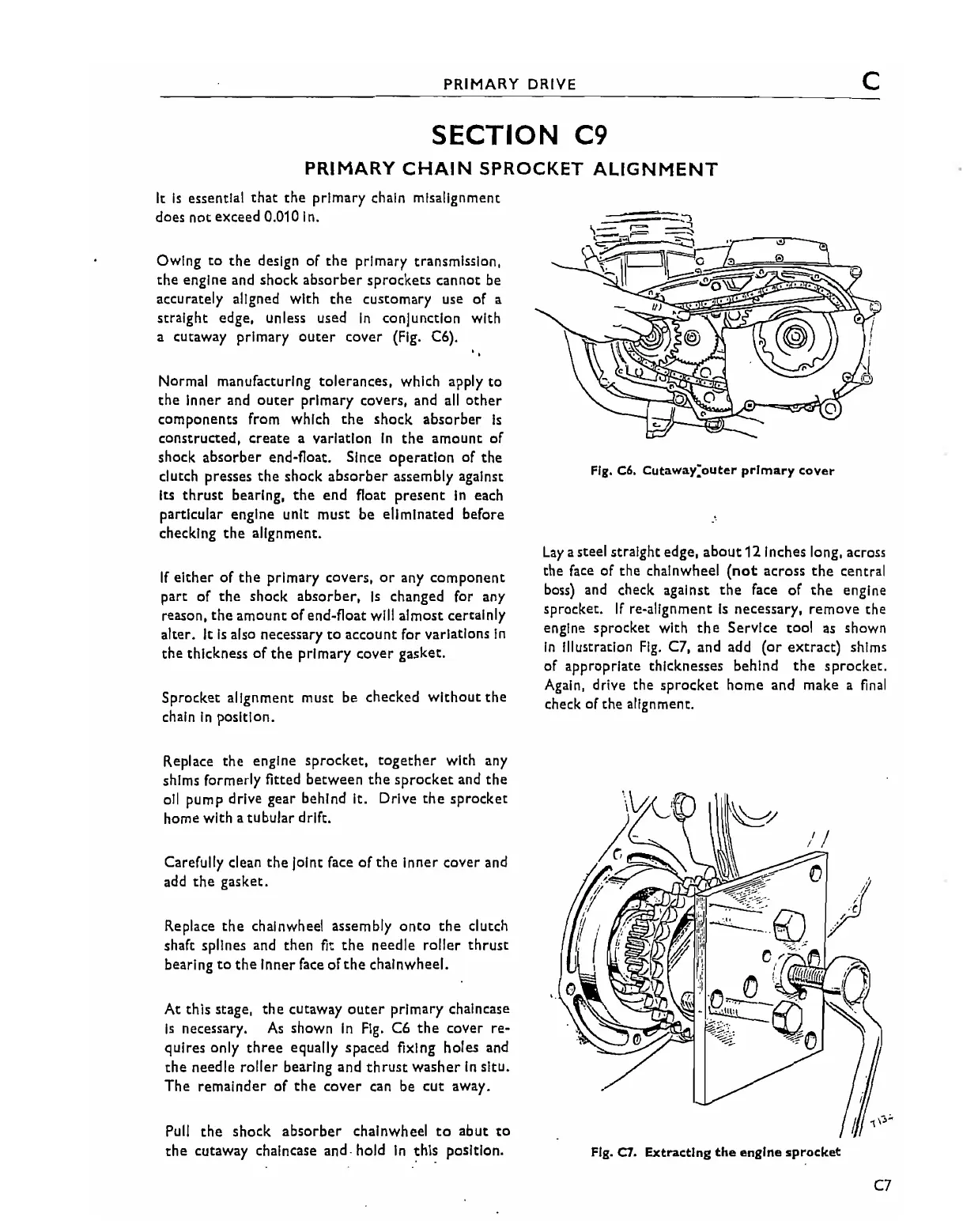
Owing
to
the
design of
the
primary transmission,
the
engine and shock
absorber
sprockets
cannot be
accurately aligned with
the
customary use of a
straight edge, unless used
In
conjunction with
a cutaway primary
outer
cover (Fig. C6).
Normal manufacturing tolerances, which apply
to
the
Inner and
outer
primary covers, and
all
other
components from which
the
shock
absorber
Is
constructed, create a variation
In
the
amount
of
shock
absorber
end-float. Since
operation
of
the
clutch presses
the
shock
absorber
assembly against
Its
thrust
bearing,
the
end
float
present
In
each
particular engine unit
must
be eliminated before
checking
the
alignment.
If
either
of
the
primary covers,
or
any
component
part of
the
shock
absorber,
Is
changed for any
reason,
the
amOunt
of
end-float will almost certainly
alter.
It
Is
also necessary
to
account for variations
In
the
thickness
of
the
primary
cover
gasket.
Sprocket alignment must be checked
without
the
chain
In
position.
Replace
the
engine
sprocket,
together
with any
shims formerly fitted
between
the
sprocket
and
the
oil pump drive gear behind It. Drive
the
sprocket
home with a
tubular
drift.
Carefully clean
the
Joint face
of
the
Inner cover and
add
the
gasket.
Replace
the
chainwheel assembly
onto
the
clutch
shaft splines and then fit
the
needle roller
thrust
bearing
to
the
Inner
face
of
the
chainwheel.
At
this stage,
the
cutaway
outer
primary chalncase
Is
necessary.
As
shown
In
Fig. C6
the
cover re-
quires only
three
equally spaced fiXing holes and
the
needle roller bearing and
thrust
washer
In
situ.
The
remainder
of
the
cover
can be
cut
away.
Pull
the
shock
absorber
chainwheel
to
abut
to
the
cutaway chalncase and. hold
In
this
position.
Fig.
C6.
Cutaway:outer primary
cover
Lay
a steel straight edge,
about
121nches long, across
the
face
of the chainwheel
(not
across
the
central
boss) and check against
the
face
of
the
engine
sprocket.
If
re-alignment
Is
necessary, remove the
engine
sprocket
with
the
Service tool as shown
In
Illustration
Fig.
C7, and add
(or
extract)
shims
of appropriate thicknesses behind
the
sprocket.
Again, drive the
sprocket
home and make a
final
check of
the
alignment.
Fig.
C7.
Extracting
the
engine
sprocket
C7