ENGINE
B
x
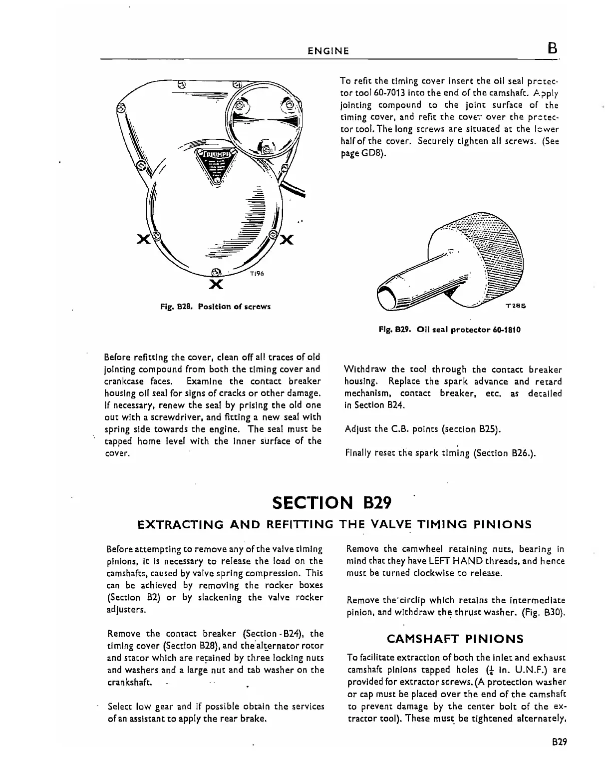
Fig,
828. Position
of
strews
Before refitting
the
cover,
dean
off
all
traces
of
old
Jointing compound from both
the
timing cover and
crankcase faces. Examine
the
contact breaker
housing
011
seal for signs
of
cracks
or
other
damage.
If
necessary, renew
the
seal
by
prlslng
the
old one
out
with a screwdriver, and fitting a new seal with
spring side towards
the
engine. The seal must be
tapped home level with
the
Inner surface
of
the
cover.
To
refit
the
timing
cover
insert
the
oil seal
prctec-
tor
tool 60-7013 Into
the
end of
the
camshaft. I-.?ply
Jointing compound
to
the
joint
surface
of
the
timing cover.
and
refit
the
COV!;";'
over
the
prctec-
tor tool. The long
screws
are
situated at
the
lcwer
half of
the
cover. Securely
tighten
all
screws. (See
page
GOB).
Fig. 829.
0/1
seal
protector
60-1810
Wlthd raw
the
tool th rough
the
contact
breaker
housing. Replace
the
spark
advance and
retard
mechanism. contact breaker.
etc.
as
detailed
In
Section
B24.
Adjust
the
C.B. points (section B25).
Finally
reset tlie spark timing (Section B26.).
SECTION
B29
EXTRACTING
AND
REFITTING
THE
VALVE
TIMING
PINIONS
Before
attempting
to
remove any of
the
valve timing
pinions.
It
Is
necessary
to
release
the
load on the
camshafts, caused
by
valve spring compression. This
can
be
achieved
by
removing
the
rocker
boxes
(Section
B2)
or
by
slackening
the
valve rocker
adjusters.
Remove
the
contact
breaker
(Section·
B24),
the
timing cover (Section
B2B),
and
theal,ernator
rotor
and
stator
which are re,alned by
three
locking nuts
and washers and a large
nut
and tab
washer
on
the
crankshaft.
Select low gear and
if
possible obtain
the
services
of
an
assistant
to
apply
the
rear
brake.
Remove
the camwheel retaining nuts, bearing
in
mind
that they have
LEFT
HAND
threads.
and hence
must be turned
clockwise
to
release.
Remove the'c1rdlp which retains
the
Intermediate
pinion. and withdraw
the
thrust
washer. (Fig.
B30).
CAMSHAFT
PINIONS
To facilitate extraction
of
both
the
Inlet and
exhaust
camshaft pinions
tapped
holes
(01-
In. U.N.F.) are
provided for
extractor
screws.
(A
protection
washer
or
cap must be placed
over
the
end
of
the
camshaft
to prevent damage
by
the
center
bolt
of
the
ex·
tractor
tool). These
mus~
be
tightened
alternately.
B29