ENGINE
B
connection
Is
located
under
the
nut
of
the
top
bolt.
Ic
is
most
essential that
this
connection
Is
replaced
on re-assembly using a
new
self locking nut.
The
small
nut
and bolt, holding
the
brake
fluid pipe
to
the engine plate, should also be removed. Unscrew
and
take
off
the
forward
adjuster
'n'Jt on
the
rear
brake pinch rod. This will
enable
the
engine
plate,
complete
with footrest,
brake
pedal and
operating
lever.
to
be lifted clear
of
the
brake
operating
mechanism and
the
frame.
To remove
the
long engine securing
bolt
from
beneath
the
crankcase,
take
off
the
nut
and spring
washer
at
the
left end,
and
withdraw
the
bolt
from
the
right side.
Note
that
on
the
right
side
there
Is
a spacer fitted
between
the
crankcase and
the
frame
tube.
Disconnect
the
horn,
then
remove
It from
the
left
front
engine bracket.
Take
off
the
nut
and washer from
the
left end
of
the
front
engine securing stud, and
withdraw
the
stud,
also
remove
the
bottom
of
the
two
bolts holding
the
left
front
engine
bracket
to
the
frame. Slacken
the
top bolt,
when
the
bracket
can
be
swung
to
one
side, as shown
In
Fig.
82.
The
bolt
can
then
be
slightly
tightened
to
hold
the
bracket
In
this
position.
The
engine
unit
Is
now
ready
to
be lifted from
the
frame,
but
owing
to
the
weight
of
the
unit,
(180
Ibs.
approximately), It
Is
advisable
to
employ
the
use
of
two
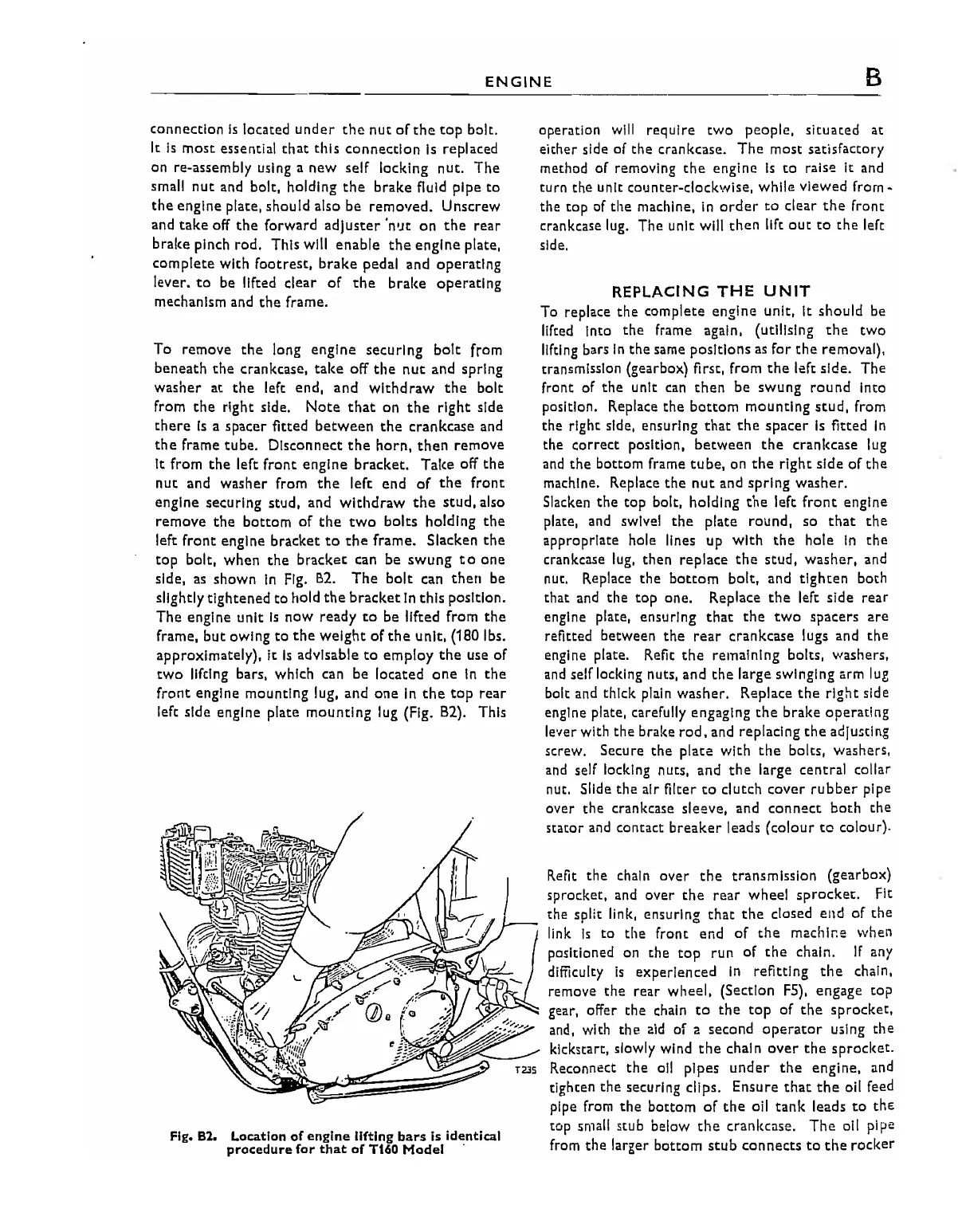
lifting bars, which can be located
one
In
the
front
engine mounting lug, and
one
In
the
top
rear
left side engine plate
mounting
lug (Fig. 82). This
Fig. 82. Location
of
engine
lifting bars is identical
procedure for
that
of
T160
Model
.
oper:J.tlon
will require
two
people, situated at
either
side
of
the
crankcase.
The
most
satisfactory
method
of
removing
the
engine
Is
to
raise
it
and
turn the unit counter-c1ock\A/ise,
while
viewed
from
...
the
top
of
the
machine,
in
order
to
clear
the
front
crankcase lug. The unit will
then
11ft
oUt
to
the
left
side.
REPLACING
THE
UNIT
To replace
the
complete engine unit, It should be
lifted Into
the
frame again, (utilising
the
two
lifting bars
In
the
same positions
as
for
the
removal),
transmission (gearbox) first, from
the
I.ft
side. The
front
of
the
unit
can
then
be
swung
round
Into
position. Replace
the
bottom
mounting
stud,
from
the right side, ensuring
that
the
spacer
Is
fitted
In
the
correct
position,
between
the
crankcase lug
and
the
bottom frame
tube,
on
the
right side
of
the
machine. Replace
the
nut
and spring washer.
Slacken
the
top bolt, holding
the
left
front
engine
plate, and swivel
the
plate
round,
so
that
the
appropriate hole lines up
with
the
hole
In
the
crankcase lug, then
replace
the
stud,
washer,
and
nut. Replace
the
bottom
bolt, and
tighten
both
that and
the
top
one. Replace
the
left side
rear
engine plate, ensuring
that
the
two
spacers
are
refitted
between
the
rear crankcase lugs and
the
engine plate. Refit
the
remaining bolts, washers,
and self locking nuts, and
the
large swinging arm
lug
bolt and thick plain washer. Replace
the
right
side
engine plate, carefUlly engaging
the
brake
operating
le'ler with
the
brake
rod,
and replacing
the
aclju5tlng
screw. Secure
the
plate
with
the
bolts, washers,
and self locking nuts, and
the
large central collar
nut. Slide
the
air filter
to
clutch
cover
rubber
pipe
over
the
crankcase
sleeve,
and
connect
both
the
stator and contact
breaker
leads
(colour
to
colour).
Refit
the
chain over
the
transmission (gearbox)
sprocket, and
over
the
rear
wheel
sprocket.
Fit
the spilt link, ensuring
that
the
closed end
of
the
link
Is
to
the
front
end
of
the
machlr:e
when
pOSitioned on
the
top
run
of
the
chain.
If
any
difficulty
Is
experienced
In
refitting
the
chain,
remove
the
rear wheel, (Section
F5),
engage top
gear, offer
the
chain
to
the
top
of
the
sprocket,
and, with
the
aid
of
a
second
operator
using
the
klckstart, slowly wind
the
chal n
over
the
sprocket.
Reconnect
the
all pipes
under
the
engine, and
tighten
the
securing clips. Ensure
that
the
oil feed
pipe from
the
bottom
of
the
oil
tank
leads
to
the
tOP
small stub below
the
crankcase.
The
oil pipe
from
the
larger bottom
stub
connects
to
the
rocker
85