BRAKES,
WHEELS
AND
TIRES
f
Ie
is
advisable to lightly
grease
the
wheel
spindle
when replacing,
so
as
to facilitate future withdrawals
of
this Item.
Refer
to
Section
F17
regarding
wheel
replacement.
The chainwheel and
the
brake
disc
are
retained
by
four long studs which pass
through
the
hub.
The
hub itself consists
of
two
halves
which
are
pressed
together
during
production.
It
Is
not
advisable
to separate
the
two
half
hubs,
otherwise
difficulty
may be
experienced
with
spoke
tensioning
'"etc.
The chainwheel
or
the
brake
disc can be
removed
without
Interfering with
the
hub
assembly itself.
SECTION
FI9
FRONT
AND
REAR
WHEEL
ALIGNMENT
When
the
rear
wheel has been fitted
Into
the
swinging arm, It must be aligned
correctly
with
the
front wheel, for
otherwise
misalignment
will cause
steering
to
be affected adversly and
both
tires
and
chains to wear
excessively.
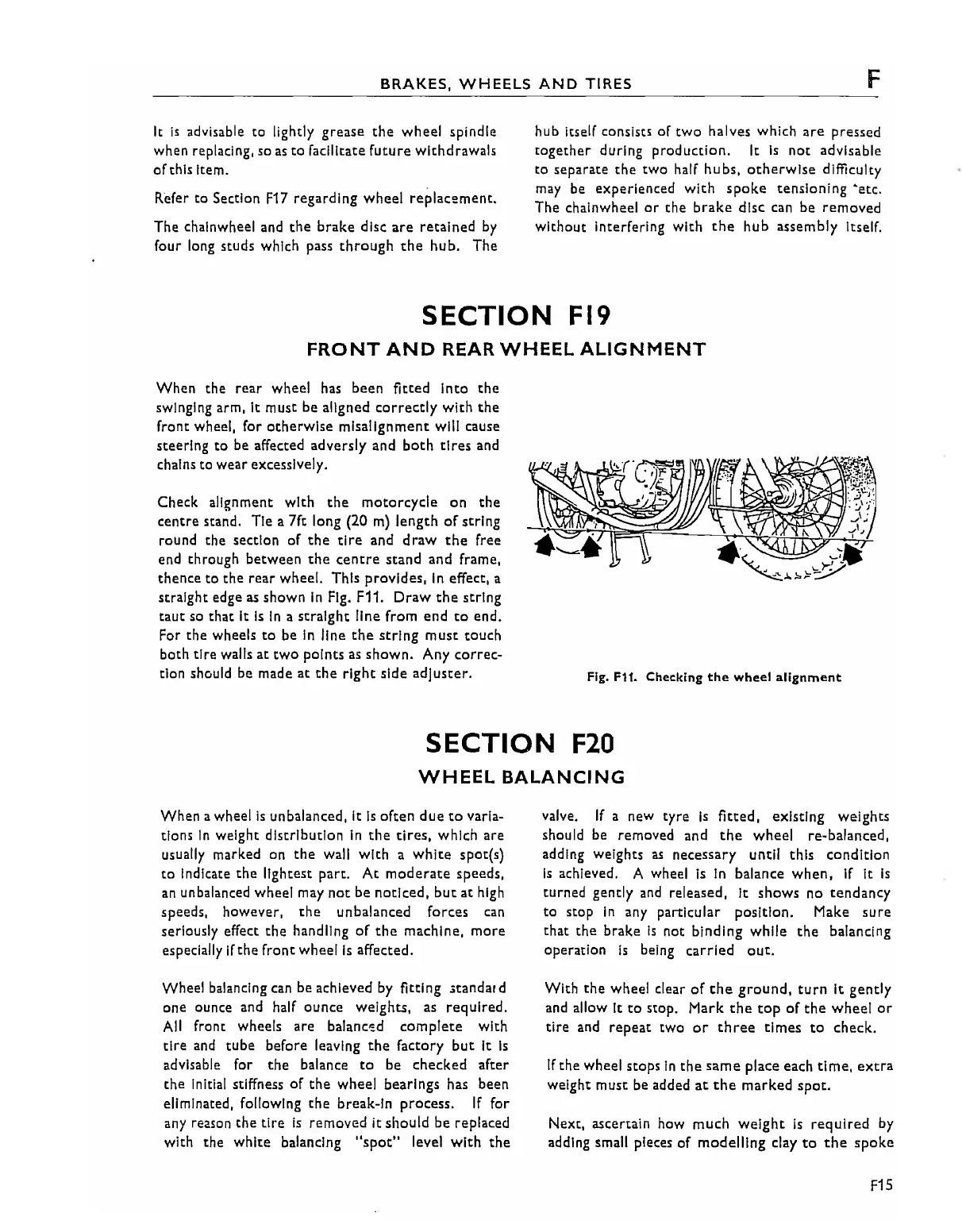
Check alignment with
the
motorcycle
on
the
centre
stand. Tie a 7ft long (20
m)
length
of
string
round the section
of
the
tire
and
draw
the
free
end through between
the
centre
stand and frame,
thence
to
the
rear
wheel. This prOVides,
In
effect, a
straight edge
as
shown
In
Fig. F11.
Draw
the
string
taut
so
that
It
Is
in
a
straight
line from
end
to
end.
For the wheels
to
be in line
the
string
muse touch
both
tire
walls
at
two
points as
shown.
Any
correc-
tion should be made
at
the
right
side
adjuster.
Fig.
F11.
Checking
the
wheel
alignment
SECTION
F20
WHEEL
BALANCING
When awheel
is
unbalanced,
It
Is
often due
to
varia-
tions
In
weight distribution
In
the
tires,
which are
usually marked on
the
wall
with
a
white
spotts)
to
Indicate
the
lightest part.
At
moderate
speeds,
an
unbalanced wheel may
not
be
noticed,
but
at
high
speeds,
however,
the
unbalanced
forces
can
seriously effect
the
handling
of
the
machine,
more
especially
If
the
front
wheelis
affected.
Wheel balancing can be achieved by fitting
.tandard
one
ounce
and
half ounce weights,
as
reqUired.
All
front wheels are balancod
complete
with
tire
and
tube
before leaving
the
factory
but
It
Is
advisable for
the
balance
to
be
checked
after
the
initial stiffness
of
the
wheel bearings has been
eliminated,
follOWing
the
break-in process.
If
for
any
reason
the
tire
is
removed
it
should be replaced
with
the
white
balancing
"spot"
level
with
the
valve.
If
a new tyre
Is
fitted,
eXisting weights
should be removed and
the
wheel
re-balanced,
adding weights
as
necessary until this condition
Is
achieved. A wheel
Is
in balance
when,
If
It
Is
turned gently and released,
it
shows
no
tendancy
to
stop
In
any particular pOSition. Make
sure
that
the
brake
Is
not
binding
while
the
balancing
operation
Is
being carried
out.
With
the
wheel clear
of
the
ground,
turn
It
gently
and allow It
to
stop. Mark
the
top
of
the
wheel
or
tire
and
repeat two
or
three
times
to
check.
If
the
wheel stops
In
the
same
place each
time,
extra
weight must be added
at
the
marked
spot.
Next, ascertain how much weight
is
reqUired
by
adding small pieces
of
modelling
clay
to
the
spoke
F15