FRAME
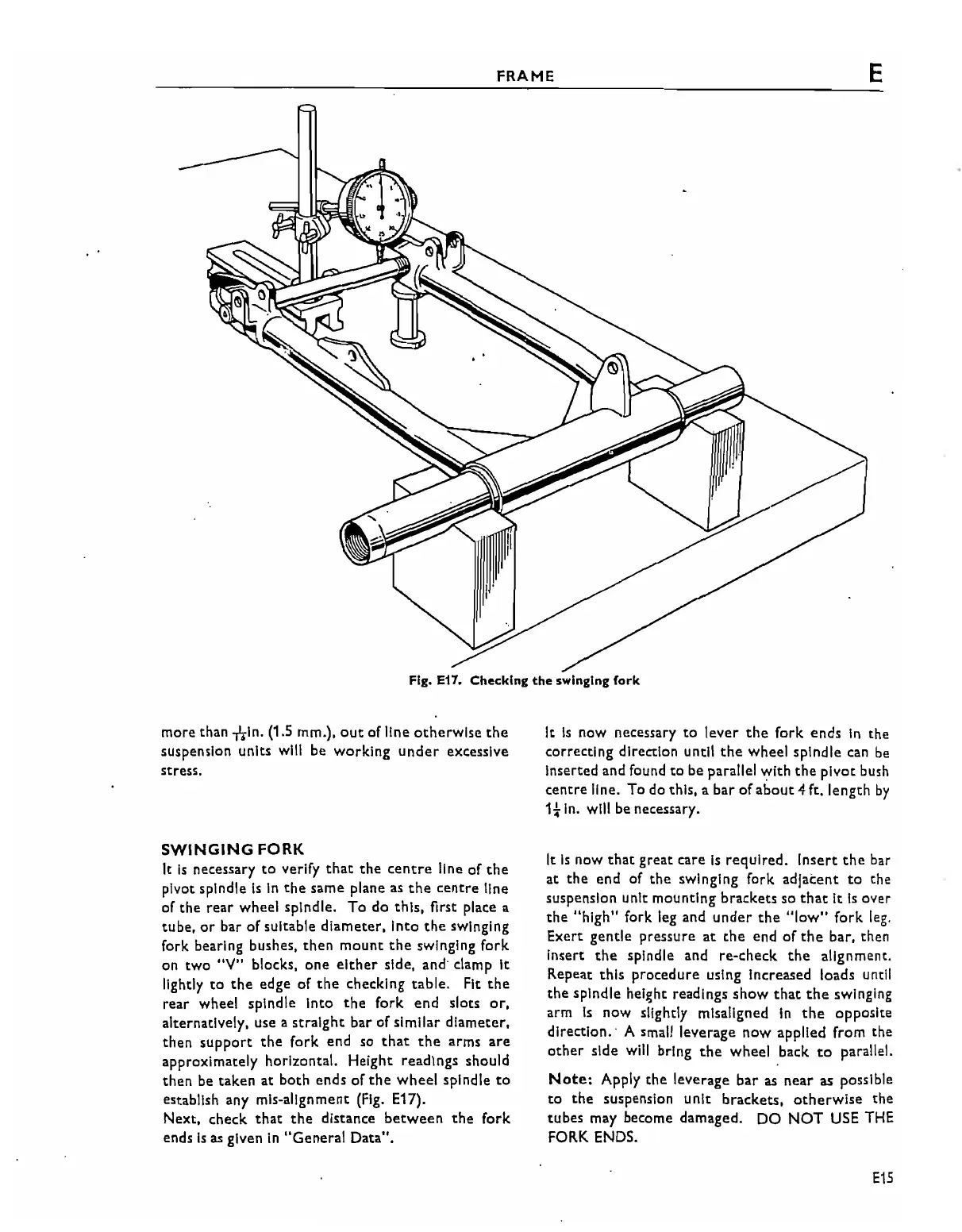
Fig. E17. Checking
the
swinging fork
E
more than
nln.
(1.5 mm.),
out
of line
otherwise
the
suspension units
will
be working
under
excessive
stress.
SWINGING
FORK
It
Is
necessary
to
verify
that
the
centre
line of
the
pivot spindle
is
In
the
same plane as
the
centre
line
of the rear wheel spindle. To do this, first place a
tube,
or
bar of suitable diameter, Into
the
swinging
fork bearing bushes,
then
mount
the
swinging fork
on two
"V"
blocks, one
either
side, and' clamp It
lightly
to
the
edge of
the
checking table. Fit
the
rear wheel spindle Into
the
fork
end slots
or,
alternatively, use a straight bar
of
similar diameter,
then
support
the
fork end so
that
the
arms
are
approximately horizontal. Height readIngs should
then be taken
at
both ends of
the
wheel spindle
to
establish any mis-alignment
(Fig.
E17).
Next, check
that
the
distance
between
the
fork
ends
Is
as
given
in
"General Data".
It
Is
now necessary
to
lever
the
fork
ends
In
the
correcting direction until
the
wheel spindle
can
be
Inserted and found
to
be parallel with
the
pivot bush
centre line. To
do
this, a bar
ofabout
4 ft. length
by
1t
In.
wl1l
be necessary.
It
Is
now
that
great care
Is
reqUired. Insert
the
bar
at
the
end of
the
swinging fork adjacent
to
the
suspension unit mounting brackets
so
that
It
Is
over
the
"high"
fork leg and
under
the
"low"
fork
leg.
Exert gentle pressure
at
the
end
of
the
bar, then
Insert
the
spindle and re-check
the
alignment.
Repeat this procedure using Increased loads until
the
spindle height readings
show
that
the
swinging
arm
is
now slightly misaligned
In
the
opposite
direction.' A small leverage now applied from the
other
side
will
bring
the
wheel back
to
parallel.
Note:
Apply
the
leverage bar
as
near as possible
to
the suspension unit brackets,
otherwise
the
tubes may become damaged. DO
NOT
USE
THE
FORK
ENDS.
E15