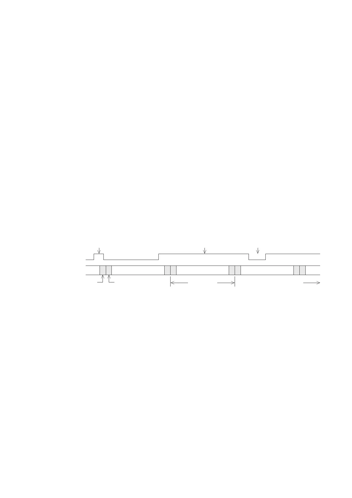
Fig. 1-4 PLC cannot read input signal which is swap over too fast
4
1-1-4 PLC Input Signals
PLC's input endpoint is a window for PLC to accept control signals from outside, and is used to interface with a variety
of switches and sensing elements. In recent years, the PLC functions have been tending to more developed
diversication, detecting elements connected with the input points are also Therefore, it is necessary for more diverse.
users to further understand the interface of PLC input point. Here are a few things to note:
1. As the PLC's work environment is often lled with a variety of noises and interfering sources, in order to work properly,
photocouplers are often used at input endpoint to isolate noises.
2. The reaction speeds of different photocouplers are varied. The High-speed photocouplers can transmit signals faster,
but the cost is higher. Therefore, high-speed photocouplers are often used at the input points of PLC which need
high-speed responses. In the rest of case, general photocouplers are used.
3. In order to prevent noise interferences, the input circuit of a PLC in addition to photocouplers, also added with lters.
Filters are divided into analog lters (composed of RC circuit) and digital lters (lter time is adjustable).
According to functional requirements the PLC inputs can be divided into high-speed and general inputs. The general
inputs are usually used in receiving signals which are not too fast, and often connected to the mechanical switchs
(signal may have bounce in action). Thus, approximately 10ms lter circuits are added with in the general inputs.
The high-speed inputs are usually designed for multiple functional inputs, those can be used as general inputs (need
longer lter time) and can also process high-speed signals (need tiny lter time). Therefore, digital lters are used
with high-speed inputs, they adjust lter time according to different needs (higher speed does not always mean better).
4. There is a time delay between the PLC's CPU received and the external signal input. The delay time is accumulated
with the aforementioned photocoupler and added lter.
5. In order to meet multiple requirements, the current PLCs are usually designed with some high-speed input
endpoints to execute some functions which require high speeds, such as high-speed counting, external
interruption, pulse capture, frequency meter and pulse measurement.
These signals usually require rapid responses and are relatively susceptible to noises. Therefore, in use, extra
attention should be paid to its wiring. To avoid interfering sources, isolation cables can be used to avoid any
interference.
6. There is certain amount of drive current at the PLC input endpoint, when using sensing elements, one must pay
attention, especially when using two-wire sensing elements.
7. PLC cannot read input signals which change too fast. For PLC, regardless of input signals, ON or OFF, its duration
must be longer than the scan time; otherwise, PLC is likely failed to read correct signals, as shown in Fig.1-4.
When input signal changes too fast to be read normally, the interrupt input function or pulse wave capture function
can be employed.
User program processing User program processing User program processing
ON OFF ON OFF
This ON signal is unreadable This ON signal is readable This OFF signal is unreadable
Input signal
Output the computed
results
Receive the external
inputs
One cycle of
“Scan Time”
Time