3-5 The MPS, MRD and MPP Instructions
MPS
(POINT STORE)
MRD
(POINT READ)
MPP
(POINT POP)
MPS
MPP
MRD
LD
MPS
AND
MPS
AND
OUT
MPP
AND
OUT
MPP
AND
MPS
AND
OUT
MPP
AND
OUT
X20
X21
X22
Y20
X23
Y21
X24
X25
Y22
X26
Y23
LD
MPS
AND
OUT
MRD
AND
OUT
MPP
AND
OUT
X0
X1
Y20
X2
Y21
X3
Y22
X21
X24
X22
X23
X25
X26
MPS
MPP
MPS
MPP
MPS
MPP
Y20
X20
Y21
Y22
Y23
MPS
MPP
MRD
X0
X1
X2
X3
Y20
Y21
Y22
84
Store the current result of the internal
PLC operation
Read the current result of the internal
PLC operation
Pop (recall and remove) the currently
stored result
Initial logical operation contact type NO (Normally Open)
Store the current result of the internal PLC operation
Serial connection of NO (Normally Open) contact
Final logical operation type coil drive
Read the current result of the internal PLC operation
Serial connection of NO (Normally Open) contact
Final logical operation type coil drive
Pop (recall and remove) the currently stored result
Serial connection of NO (Normally Open) contact
Final logical operation type coil drive
The MPS instruction stores the state of a connection point of the ladder circuit so that further coil branched can recall the
value later.
The MRD instruction recalls or reads the previously stored connection point data and forces the next contact to connect to
it.
The MPP instruction pops (recalls and removes) the stored connection point data of the last array and removes the
connection point from the result. The last contact or coil circuit must connect to an MPP instruction.
In any continuous connection circuit block, the difference between the number of the active MPS instruction and the
number of the active MPP instruction shall be no greater than 11; when all connection circuit blocks are ended, the total
number of the MPS instruction and the total number of the MPP instruction have been used in the program must be the
same (there must has a MPP instruction corresponding to every signal MPS instruction).
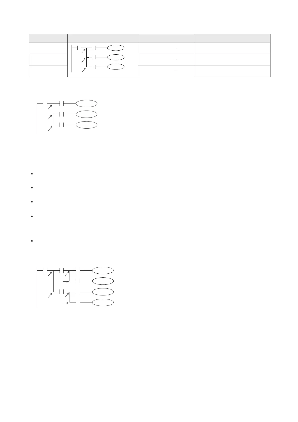
The following diagram shows the program example block with three connections:
Mnemonic Devices Function Format
Ladder Diagram
Instruction List
Ladder Diagram
Instruction List