X0
X1
X2
X3
X4
X5
X6
X7
IX0P
IX1P
IX2P
IX3P
IX4P
IX5P
IX6P
IX7P
M9050
M9051
M9052
M9053
M9054
M9055
M9056
M9057
IX0F
IX1F
IX2F
IX3F
IX4F
IX5F
IX6F
IX7F
※ One external input point only corresponds to one external interrupt pointer. Such as either the IX0P or IX0F can be
used in a program; either the IX1P or IX1F can be used in a program, and so forth.
Y0
SET
M9000
IRET
FEND
IX1F
REF Y 0 K 8
The main program.
The First End instruction. End of the main program.
The IX1F external interrupt pointer.
Set the Y0 ON.
Deliver the memory's status to the
outputs Y0~Y7 immediately.
The end of interrupt subroutine and return.
The IX1F external interrupt subroutine.
MOV KX X X D 9 1 6 3
M9163
IX0P
The interrupt subroutine
Delay time, unit: ms,
can be assigned by a K, D or R.
IRET
The actual timing
of the subroutine
is operated
Delay time
IRET
The tables below list the special relay and register related to this function:
■
Represents that component is read only.
D9163
■
M9163
External Interrupt delay time set-up ag. Use this ag contact to active the interrupt delay function.
External interrupt delay time set value ( Unit: ms).
54
2-15-1 External Interrupt
The VS Series PLC has 8 external interrupt input points X0~X7. The External Interrupt function can be employed when
the external input signal that needs instant response, not to be affected by scan time or to read a narrow width pulse.
The External Interrupt signal works with its corresponding interrupt subroutine to execute an external interrupt.
The External Interrupt pointers are listed in the following table:
External Input Point
Rising Edge Interrupt Pointer Falling Edge Interrupt Pointer Interrupt Prohibit Flag
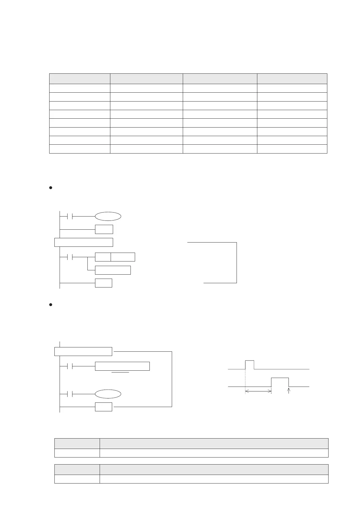
Program example:
When the external input point X1 turns OFF, the IX1F interrupt subroutine is executed and Y0 is set to ON. And the
status of Y0 ON is immediately sent to the output port via the I / O refresh command REF (FNC 50).
The VS series PLC external interrupt has the function of delay interrupt. That delay time is by the unit of 1ms.
This feature allows the user to change the starting of the interrupt subroutine by the parameter adjustments, without
to change the external detector's location where the interrupt signal has occurred.
This interrupt delay time setting is by a series of particular pattern below the interrupt pointer. The pattern format of
this standard program can not be changed.
Interrupt Input
X0~X7
Register ID No.
Description
Description
Relay ID No.