If the OUT instruction is used for the coil of the component T or C, input a Set Value is required.
Timer
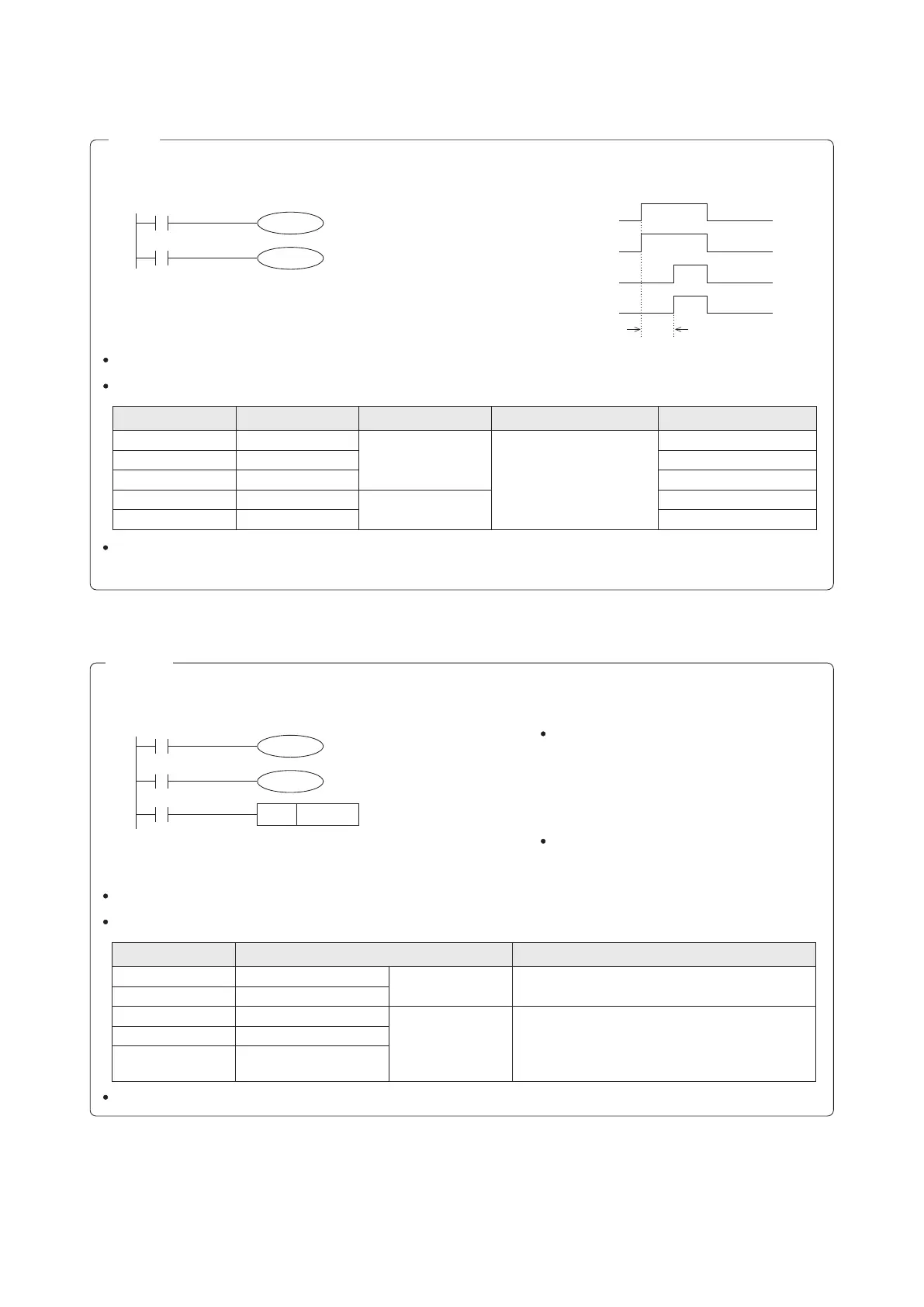
LD
OUT
LD
OUT
X0
T0
K20
T0
Y20
The Set Value of a Timer can be set by either using a K (Constant) or a Data Register D, R (Parameter).
The available range of the Set Value:
Counter
Action Description
LD
OUT
LD
OUT
LD
RST
X0
C0
K5
C0
Y20
X1
C0
The Set Value of a Counter can be set by either using a K (Constant) or a Data Register D, R (Parameter).
The available range of the Set Value:
C0~C99
C100~C199
C200~C219
C220~C234
C235~C255
General
Latched
General
Latched
Software High Speed Counter
(Latched)
16-bit
Up count
32-bit
Up/Down count
1~32,767
(The Set Value beyond this range will be defaulted to 1)
–2,147,483,648~2,147,483,647
To reset the contact or Present Value of a Retentive Timer T246~T255, must use the RST instruction.
Counter ID No.
Type of the Counter
Available Range
When using High Speed Counters, please refer to the section 2-7 High Speed Counter.
When the X0 is turned from “OFF” to “ON”,
the C0 executes up count once, until the
Present Value of the C0 is equal to 5 that will
turn its output contact to “ON”, where the
Present Value will not increase anymore and
its contact will stay permanently “ON”.
When X1= “ON”, the Present Value of C0 will
be reset to “0” and the contact of C0 will
become “OFF”.
X0
T0 coil
T0 contact
Y20
2 sec
Timer ID No.
Timing Unit
Type of Timer
Available Range
Real Setting Time
T0~T199
T200~T245
T246~T249
T250~T255
100ms
10ms
1ms
100ms
General Timer
(non-retentive)
Retentive Timer
1~32,767
(The Set Value beyond this
range will be defaulted to 0)
※
0.1~3276.7 sec.
0.01~327.67 sec.
0.001~32.767 sec.
0.001~32.767 sec.
0.1~3276.7 sec.
T256~T511
1ms
X0
T0
K20
T0
Y20
C0RST
C0
K5
Y20
X0
C0
X1
87
3-9 The OUT and RST Instructions for the Timer or Counter
Active I/O duration time sheet
Ladder Diagram
Instruction List
Ladder Diagram
Instruction List
※ If the timer's Set Value is 0, its contact will become activated at the next scan time after its coil is triggered.