408
0
b0
b1 b2
b3
b4
b5 b6
1
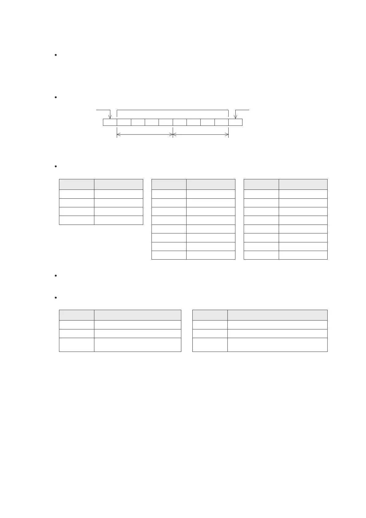
START
DATA 8 bits
STOP bit
LOWER
HEX digit
UPPER
HEX digit
b7
ASCII Code
STX
ETX
ACK
DLE
02H
03H
06H
10H
ASCII Code ASCII Code
0 8
1
9
2
3
4
5
6
7
A
B
C
D
E
F
30H 38H
31H 39H
32H
33H
34H
35H
36H
37H
41H
42H
43H
44H
45H
46H
00H
02H
04H
08H
31H
06H
7-4 VS Series PLC Communication Protocol
A. The relevant communication parameters
Bits-per-character: 8 bits
Parity check: None
Stop bit: 1 bit
Baud rate: 300/600/1200/2400/4800/9600/19200/34800/57600/115200 bps. selectable (default: 19200 bps.)
Syntax of a communication character
This communication protocol adopted the mixed method of ASCII and the HEX code to transmit data. This protocol
adopts a few ASCII codes, the conversion table below shows those characters and the corresponding ASCII codes.
Character Character Character
Communication station number:
The available station number is between 0~254 (default: 0). If the communication command uses the station
number 255, that is a broadcast command.
Error code: When data string is feedback from a PLC, will include with an error code. The table lists the meaning of
every error code.
Error Code
Description
Error Code
Description
Communication is normal; no error
Communication SUM Check Error
The number of data bytes or the
number of components is 0
The number of data bits exceeds the range
Error ASCII conversion
The command / function code is not existed