The data register can be distinguished by its use as follows:
The characteristics of the Data Register D and the Extension Register R are identical, so hereafter referred to as a Data
Register. The data register is used to store a numerical data. The data length is 16 bits and the Most Significant Bit
represents a positive/negative sign. A register can store a content value between -32,768 and +32,767. Also, that is
possible to combine two 16-bit registers into a 32-bit one; the 16 bits with a smaller number is defined as the lower 16
bits and the larger number is the upper 16 bits. A 32-bit data register can store a content value between -2,147,483,648
and +2,147,483,647, the Most Significant Bit represents a positive/negative sign.
(1) General Register
(2) Latched Register
When the PLC turns from RUN to STOP or its power is cut out the data in the register is reset to zero. If the M9033
is ON then the PLC turns from RUN to STOP, the data will retain; however, when the power is cut out, the data will
still be cleared and become “0”.
When the PLC's power is disconnected, the data in the Latched Register will be maintained as same as the value
stored before the event occurred.
To clear the contents in the Latched Register, could use the RST or ZRST instruction.
The main purposes of the Latched Register are to store setup data, record data and the memory of mold parameter.
When the number of Latched Register is not enough or the stored data has the demand to be transplant, should
use the expanded memory card and put the data into the card.
Since the memory card uses Flash ROM to store data, the number of writes is limited to 100,000 times. The
improper use may shorten the lifespan of the Flash ROM. Therefore, use the DBWRP to substitute the DBWR
instruction in a program to write data, that could avoid unnecessary operations and extend the lifespan of the
Flash ROM.
The VS series PLC provides the VS-MC and VS-MCR memory cards. After the installation of a memory card,
655,360 words of latched data storage space are available. Data can be transferred between the data register
and the memory in the card via the data bank write instruction DBWR (FNC 91) and the data bank read
instruction DBRD (FNC 90).
(3) Special Register
Each Special Register has its own specific function, the main usage is as the storage of system status, error code
or status monitoring. For details, please refer to the section 2-14 “Special Relay and Special Register”.
VS series Memory Cards
(4) Extension Register
When the PLC turns from RUN to STOP or its power is cut out the data in the register is reset to zero.
If the M9033 is ON then the PLC turns from RUN to STOP, the data will retain; however, when the power is cut out,
the data will still be cleared and become “0”.
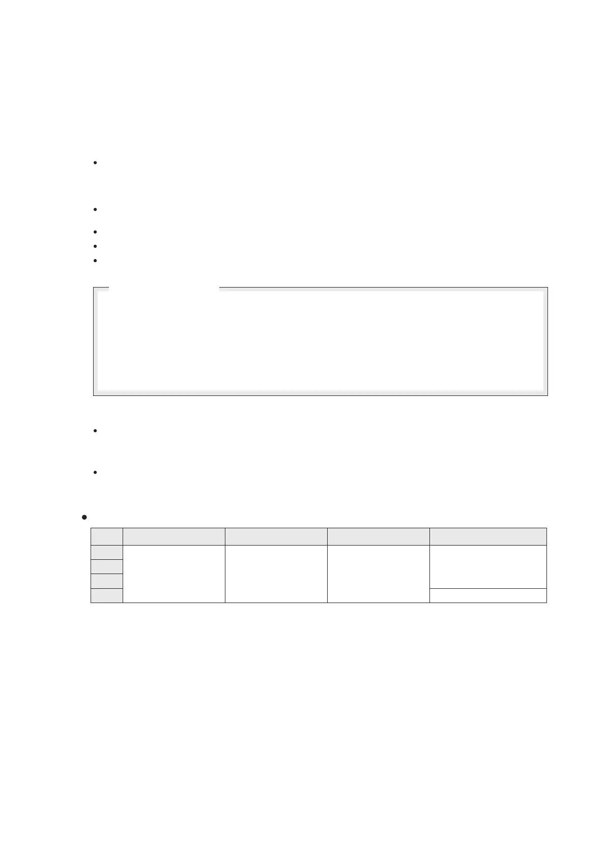
The function and discrimination of registers D in the VS1, VS2, VSM and VS3 series are exactly the same:
D0~D6999
Tot.= 7000Pt.
D7000~D8999
Tot.= 2000 Pt.
D9000~D9511
Tot.= 512 Pt.
R0 R9999 Tot.= 10000 Pt. ~ ,
R0 R25999, Tot.= 26000 Pt. ~
VS1
VS2
VSM
VS3
31
2-8 Data Register (D) and Expansion Register (R)
Series
General Register
Latched Register
Special Register
Extension Register