72
BFM No.
#20
#21
#22
Component Description
To assign the analog output modes of AO1~AO2. When the power is turned from OFF to ON, the default value is H00.
When the power is turned from OFF to ON, the default value is 0.
#23
#30
#31
To assign the holding modes of AO1~AO2. When the power is turned from OFF to ON, the default value is H00.
Identication code: VS-2DA = K202 (can use the FROM instruction to check whether the place is this module or not)
The version number of this module. (the content value XX indicates Ver. X.X)
The digital set value of AO2.
The digital set value of AO1.
BFM#23 To appoint the output holding mode: (for the PLC status turns from RUN to STOP)
b15 b0
AO2 AO1
BFM#23
If the value in the nibble = 0, the channel will keep the last output, even PLC
is STOP.
If the value in the nibble ≠ 0, the channel will change its digital set value = 0
at STOP.
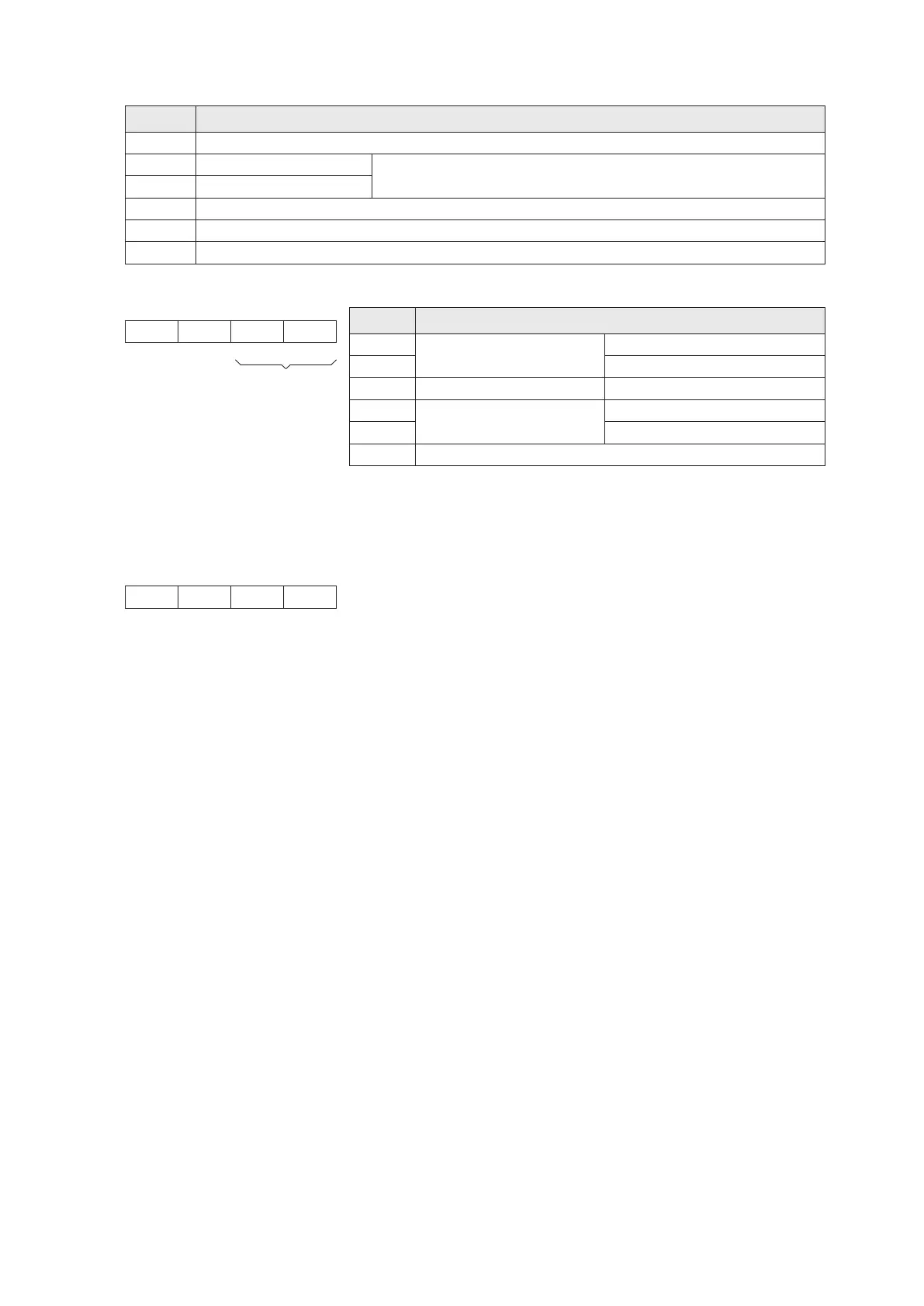
BFM#20 To appoint the modes of analog outputs:
Example: If the BFM #20 of a VS-2DA is set to be H20, then
AO1: For –10V~+10V voltage output, that will use the digital set value –32,000~+32,000 at this mode.
AO2: For 4mA~20mA current output, that will use the digital set value 0~+32,000 at this mode.
Value of
Nibble
0
1
2
3
4
Other
Disabled
–20mA~+20mA current output
–10V~+10V voltage output
4mA~20mA current output
Analog Output Mode
Digital set value: –32000~+32000
Digital set value: –10000~+10000
Digital set value: 0~+32000
Digital set value: –32000~+32000
Digital set value: –20000~+20000
b15 b0BFM#20
Null
To assign
output modes
AO2 AO1Null
Nibble #4
Nibble #3
Nibble #2 Nibble #1
Nibble #4
Nibble #3
Nibble #2 Nibble #1
NullNull
2-17-2 Buffer Memory BFM in the VS-2DA Module