Index Register V, Z is a very special register in the VS series PLC. Its purpose is to use the index to modify the operand
in an instruction, to serve the purpose of specifying the operand indirectly and exchangeable, thereby improving the
flexibility and efficiency of program editing.
The index register provides the ability to specify the operand with flexibility when the instruction is being executed. That
providing great help in the preparation of complex control program, and can often simplify the process. Here are some
possible applications for reference:
(1) At the Subroutine. There is generally a need for a subprogram to perform the same function repeatedly for different
operands.
(2) The instruction in the program has limitation about the used number of times.
(3) When the data in bulk needs process, the source or target data can be specified by the index register.
The index register is a 16-bit register, numbered from the V0 to the V7 and from the Z0 to the Z7, 16 points in total.
V, Z registers can be paired up to form a 32-bit register. In the 32-bit application instruction, V, Z registers should be
paired up as (V0, Z0) (V1, Z1)..... (V7, Z7); in specifying the operands, only Z register needs to be assigned.
16-bit
Upper 16 bits Lower 16 bits
32-bit
The Index Registers can be used to modify the operand in a basic instruction, the modifiable components are shown
below:
The set value of T: when it uses K, D or R at the OUT coil.
The set value of C: when it uses K, D or R at the OUT coil.
Here provide some examples that Index registers V, Z modify operands:
When Z0=10, X0Z0=X12 (The X is named by octal number system)
Y5Z0=Y17 (The Y is named by octal number system)
M10Z0=M20
S2Z0=S12
K100Z0=K110
D0Z0=D10
16-bit
Z0
Z1
Z2
Z3
Z4
Z5
Z6
Z7
V0
V1
V2
V3
V4
V5
V6
V7
V0
V1
V2
V3
V4
V5
V6
V7
Z0
Z1
Z2
Z3
Z4
Z5
Z6
Z7
In the 32 bits instructions, only the Z0
needs to be specified.
When Z0 = V0 = 0, X0 drives the T0 timer and D0 is the set value.
When Z0 = 1 and V0 = 2, X0 drives the T2 timer and D1 is the set value.
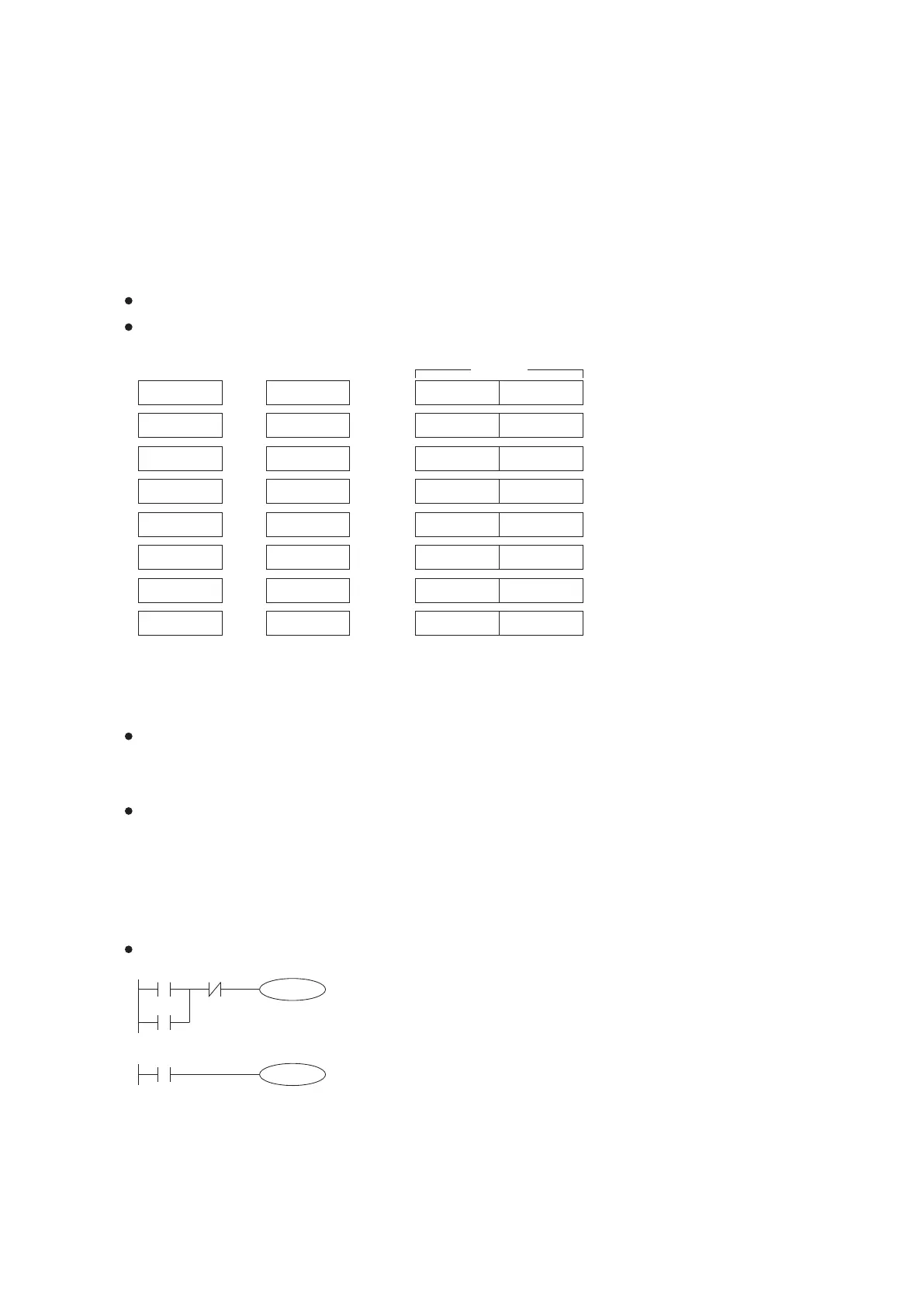
Examples of using index register in basic instructions:
As shown in the left diagram it is a self-holding circuit.
When Z0 = 0, that triggers by X0, releases by X1 and has an output at Y0.
When Z0 = 5, that triggers by X5, releases by X6 and has an output at Y5.
X0Z0
Y0Z0
X1Z0
Y0Z0
X0
T0V0
D0Z0
32
2-9 Index Register (V and Z)
2-9-1 Using Index Register in Basic Instruction