421
DOG Signal
CLR Signal
The DOG signal may use a X or M. Usually assigned to the X0~X7, because by the interrupt input
point can have the precise home position. On the other hand, if the signal for the DOG is not from
X0~X7, the home position after the return will have some inaccurate error.
The CLR signal output can assign to a Y or M, the width of that “ON” signal is ≥ 20ms.
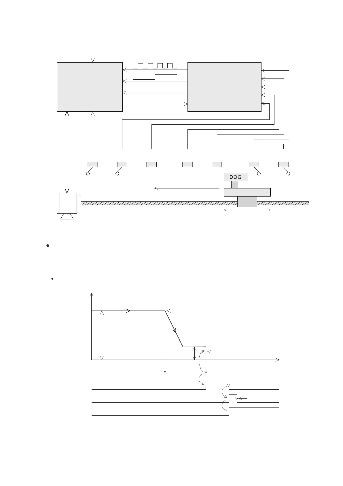
8-1-3 Positioning Operation Setting Up
Demonstrated below is the brief conguration of a general positioning control system, which we will use to illustrate the
related parameter settings for the positioning control.
Home Position Return (Zero Return)
The VS PLC provides a variety of home position return modes when the ZRN instruction is used, which will be
explained one by one below. The parameters in the setup sheet are decided on those different modes. Hence, to
easily complete the setting, all the users need to do is to select the appropriate mode, and then ll in the relevant
parameters.
DOG Rear End home positioning
Speed
Direction of home positioning
DOG Front End, start to slow down
Home positioning speed
Home positioning creep speed
Stop immediately when DOG's Rear End comes
Time
Positioning
completed ag
Condition contact “OFF”
Home positioning
complete ag
LSF
Forward limit
switch
DOG
Near point
signal
LSR
Reverse limit
switch
CLR
PG0
Servo motor drive
VS series
PLC
DV2I
Speed change
signal
INT
Interrupt
signal
Pulse output
Direction output
Clear signal
Zero point signal
Direction of home positioning
Sliding table
Servo
motor
Driving screw
LSR
Reverse limit
switch
LSF
Forward limit
switch