In general, the PLC executes user program in the way of sequential scanning. Even the system itself also follows a
sequence of execution (receive external inputs → process the user program → output the computed results).
However, such an ordinary operation is occasionally unable to meet the needs for quick control responses. Therefore,
the interruption function is generated which meets the required of to cut-in a processing sequence immediate.
The interrupt, as the name suggests, is to break the sequentially executed program, and then insert a program section
to be processed immediately. In the VS series PLC, every Interrupt Pointer is bound up with its interrupt subroutine to
deal with the user's requirement for the insertion of interruption.
The purpose of the Interrupt Pointer is to specify the start position of interrupt subroutine in the program.
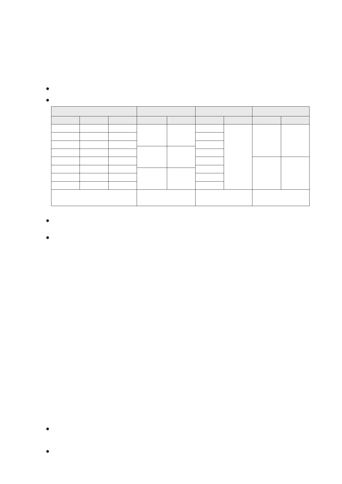
The ID numbers of Interrupt Pointer I in the VS1, VS2, VSM and VS3 series are exactly the same:
External Interrupt Timer Interrupt
Software HSC Interrupt
External Input Interrupt Pointer
X0
X1
X2
X3
X4
X5
I
X0
□
I
HC0
I
HC1
I
HC2
I
HC3
I
HC4
I
HC5
I
HC6
I
HC7
I
TA
□□
I
TB
□□
I
TC
□□
I
X1
□
I
X2
□
I
X3
□
I
X4
□
I
X5
□
I
X6
□
I
X7
□
=P means interrupt on the rising edge
=F means interrupt on the falling edge
□
□
□□=01~99 means
the interval time is 1~99ms
X6
X7
Inhibit Flag
M9050
M9051
M9052
M9053
M9054
M9055
M9058
M9061
M9056
M9059
M9057
M9060
Hardware HSC Interrupt
I
HHC1
I
HHC2
M9062
M9063
The interrupt is processed
with the DHSCS instruction.
When the present value
reaches to the set value, the
interrupt can be processed.
Each interrupt pointer has an inhibitory special relay to control the interrupt, the user can avoid the interrupt by
activating the corresponding special relay.
By the characteristics, those interrupt pointers can be divided into external interrupt, timer interrupt, software
high-speed counter interrupt and hardware high-speed counter interrupt.
① External Interrupt:
The rising or falling signal from the specific input point (X0 to X7) generates an interrupt signal to interrupt the
program in execution, jump to a designated interrupt pointer (IX0 □ to IX7 □ ) and execute a corresponding
interrupt subroutine. The External Interrupt at the VS series PLC also has the delay action function.
Please refer to “2-15-1 External Interrupt” for more details.
② Timer Interrupt:
When the timer interrupt pointer (ITA □□ , ITB □□ or ITC □□ ) is written into the program, the PLC will
automatically interrupt the program execution at a given time (as defined by the □□ in the interrupt pointer).
Its procedure jumps to the appointed interrupt pointer and executes the interrupt subroutine.
Timer interrupt is mainly used to generate a repeated interrupt that could execute fixed and rapid period timing
subroutine. When a certain section is requiring an execution cycle shorter than the PLC's scan time or a fixed time
cycle, the timer interrupt is considered.
For example, the HKY (FNC71) and SEGL (FNC74) instructions can use the PLC's scan time as the scan cycle of
the instructions. However, too long or too short scan time may cause fault. In this case, a timer interrupt
subroutine can be used to perform appropriate scan operation.
Additionally, the RAMP (FNC67) instruction generally depends the scan time of the program to bring the movement
of ramp steps forward. Usually, the scan time is unregulated, thus the generated ramp result will become irregular.
In this case, a subroutine of timer interrupt can be used for the RAMP instruction to depart it from the scan time,
that may stabilize the movement of step thus to produce the regular ramp result.
③ Software High Speed Counter Interrupt:
The result of a comparison instruction by the FNC53 (DHSCS) high-speed counter can be assigned to execute an
interrupt subroutine. When the DHSCS instruction is assigned to execute a certain interrupt subroutine
(IHC0~IHC7) and the comparison result is equal, then PLC will jump to the specified interrupt pointer and execute
the interrupt subroutine. Please refer to the FNC53 (DHSCS) Instruction for more details.
④ Hardware High Speed Counter Interrupt:
When the hardware high-speed counter HHSC1 reaches its set value by the external input, the IHHC1 interrupt can
be generated; also, the HHSC2 can generate the IHHC2 interrupt. Please refer to “2-15-4 Hardware High-Speed
Counter”.
The interrupt subroutine often needs to immediately read the external state or immediately drive the external load. In
this case, the I / O update instruction REF (FNC 50) should be used in the interrupt subroutine to update the I / O
status promptly.
In the interrupt subroutine, should use the Timer T192~T199 when a timer is necessary.
37
2-12 Interrupt Pointer (I)
Interrupt Pointer
Inhibit Flag
Interrupt Pointer
Inhibit Flag Inhibit Flag
Interrupt Pointer