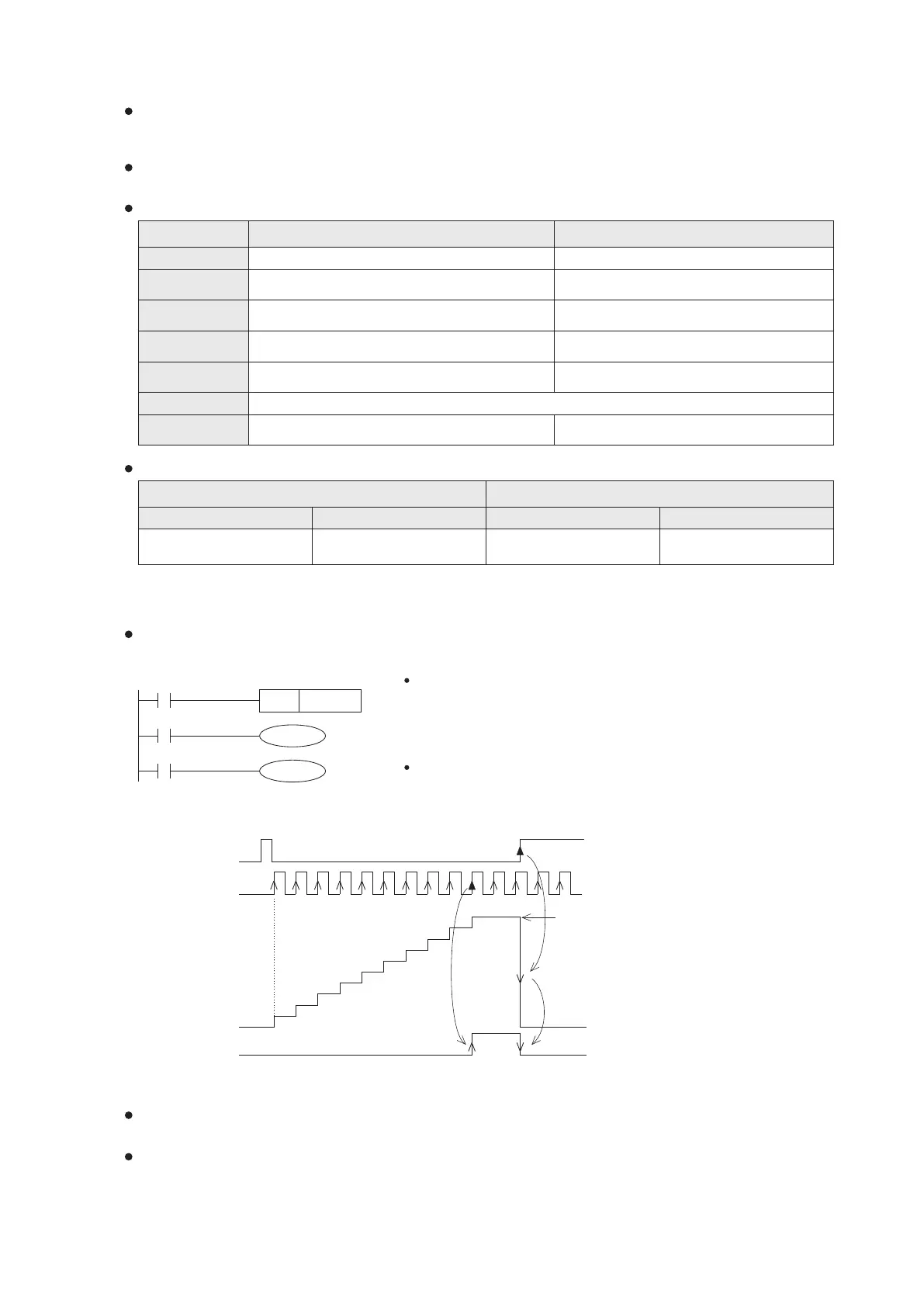
X1
C0
C0
Y0
K10
X0
RST C0
The contact signal X1 is to drive the C0 counter. When the signal X1
turns from OFF to ON once, the present value of C0 will increase by 1.
Then, on the tenth input turning ON, C0's output contact is activated,
turns ON. After that, the present value remains unchanged even the X1
changes.
When the pulse input signal in a counter turns from OFF to ON, the present value of the counter will increase (+1 in a
up count) or decrease (-1 in a down count) each time, based on the counting types of counters. If the present value
equals to set value, the counter's contact turns to be ON.
The counrer's set value can be set directly by using a constant number K or indirectly by using the content value that
stored in the register D, R. Also, this can be modified by the Index Register V/Z.
The characteristics of the 16-bit and 32-bit counters are shown in the following table:
Item
1 6- bit counter 3 2- bit counter
Count Direction
Available Set Value
Set Value Appoint
Changes of
Present Value
Reset Action
Present Value
Register
Up count
1~32,767 (equivalent to 1, if the set value exceeds the
range)
Constant K or a data register
Increase; retain if reaching the set value
Turns ON & retains if the current value reaches the set value
When the RST instruction is executed, the present value becomes “0” and the contact will turn to be OFF.
16 bits
Up or Down Count, bi-directional
-2,147,483,648~ +2,147,483,647
Same as in the left column, but each 32-bit
value ocupies 2 data registers
Continuing changing once reaching the set value
Up count: turns ON if reaches the set value
Down count: turns OFF if passes through the set value
32 bits
Status of Contact
General
Latched
C0~C99
100 Pt.
C100~C199
100 Pt.
C200~C219
20 Pt.
C220~C234
15 Pt.
The present value of a general counter will be reset when a PLC encounters power cut off. However, the latched
counter will retain its present value before the power is cut off and starts from there when it is powered.
The counter's set value can be set by using a constant K directly or a content value in the Data Register D, R
indirectly. Also, this can be modified by the Index Register V/Z.
When the MOV instruction transfers a new present value to the counter and which is greater than its set value, the
counter's contact will turn to be ON promptly at the next input signal is ON, and meanwhile the present value will
become the same as the set value.
When reset signal X0 is ON, the RST instruction operates. The present
value of C0 is reset to “0” and its contact will become OFF.
The definition of counters at the VS1,VS2,VSM and VS3 serie are exactly the same:
22
Present value of C0
0
1
2
3
4
5
6
7
8
9
10
Reset signal
X0
Count signal
X1
Set value
Y0
2-6 Counter (C)
1 6- bit counter 3 2- bit counter
General
Latched
2-6-1 16- bit Counter