420
8-1-2 Basic Parameters
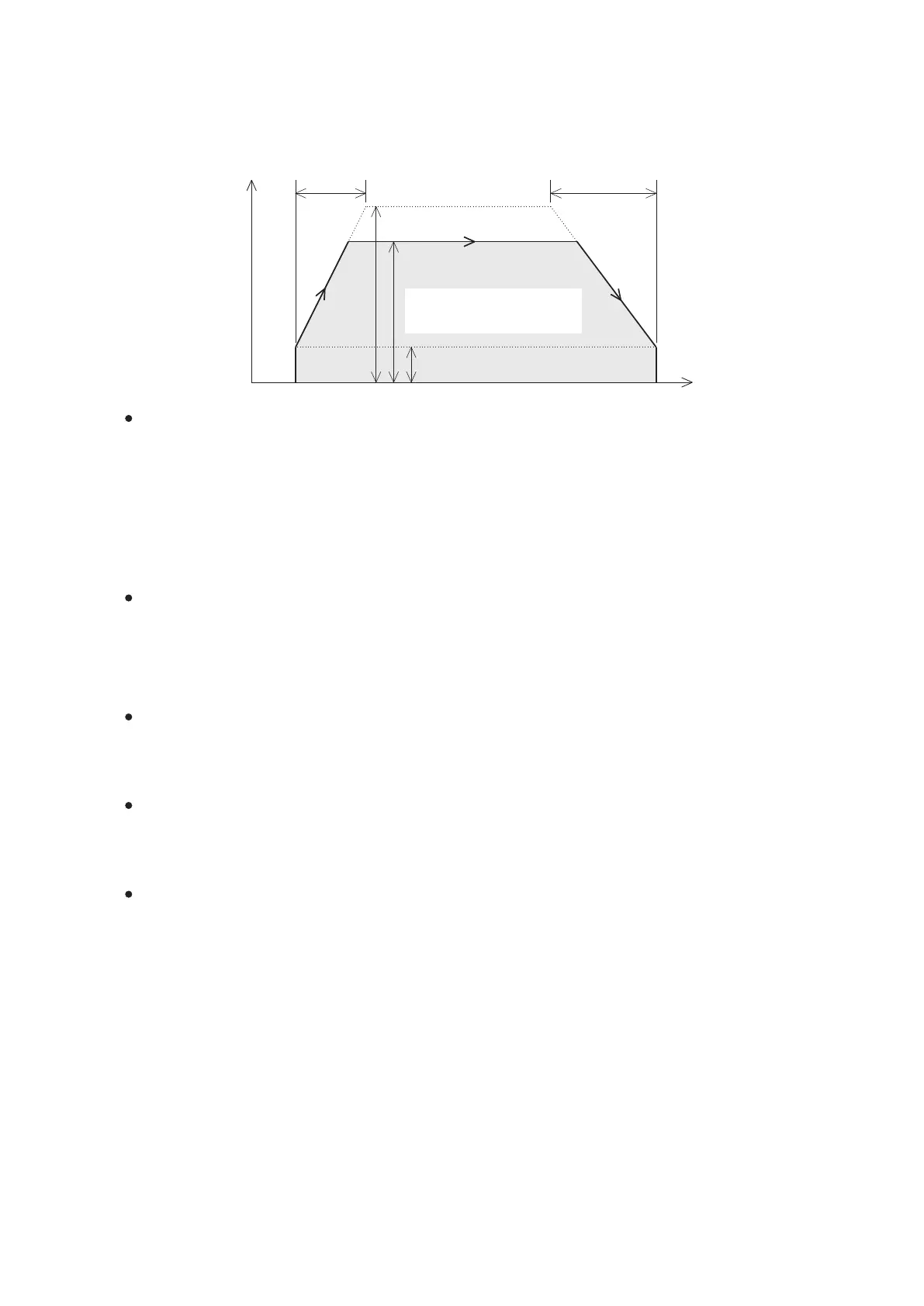
The VS series PLC provides the positioning control with the acceleration and deceleration functions, as shown in the
following diagram. It is necessary to set relevant parameters before to use the positioning control instructions, thus can
perform the operation correctly. The parameters in the diagram below uses Y0 output axis as an example.
Speed
(Frequency)
Acceleration time
(D9343)
Deceleration time
(D9344)
Maximum speed (D9341,D9340)
Operating speed
Bias speed (D9342)
Time
Maximum speed
This value connes the highest limit of the positioning control speed at a certain axis. If its operation speed exceeds
the limit of the maximum speed during the action of any positioning control instruction, the instruction will be operated
according to the maximum speed.
The highest output frequency of the VS1 or VS2 series is 50 kHz. The acceptable value range is from 1 to 50 k (Hz).
Any value less than 1 is regarded as 1 Hz; more than 50 k is regarded as 50 kHz. The default value is 50 kHz.
The highest output frequency of the VSM or VS3 series is 200 kHz. The acceptable value range is from 1 to
200 k (Hz). Any value less than 1 is regarded as 1 Hz; more than 200 k is regarded as 200 kHz. The default value is
200 kHz.
The highest output frequency of the VSM-28ML series is 1 MHz. The acceptable value range is from 1 to 1 M (Hz).
Any value less than 1 is regarded as 1 Hz; more than 1 M is regarded as 1 MHz. The default value is 1 MHz.
Bias speed
This value connes the lowest limit of the positioning control speed at a certain axis. The main purpose is to avoid the
low-frequency resonance area of a step motor. Thus, it is usually set to be 0 for a servo motor.
If the operation speed is lower than the bias speed during the action of any positioning control instruction, the
instruction will be operated according to the bias speed.
The acceptable value range is from 0 to 20 k (Hz). Any value less than 0 is regarded as 0 Hz; more than 20 k is
regarded as 20 kHz. The default value is 0 Hz.
Acceleration timey
As shown in the diagram, the acceleration time refers to the time it takes for speeding up from the bias speed to the
maximum speed (not the operating speed).
The acceptable value range is from 0 to 32,000 (ms). Any value less than 0 is regarded as 0 ms; more than 32,000 is
regarded as 32,000 ms. The default value is 100 ms.
Deceleration time
As shown in the diagram, the deceleration time refers to the time it takes for slowing down from the maximum speed
(not the operating speed) to the bias speed.
The acceptable value range is from 0 to 32,000 (ms). Any value less than 0 is regarded as 0 ms; more than 32,000 is
regarded as 32,000 ms. The default value is 100 ms.
Rotational direction
Users can select the direction control pattern: “Increase present value when forward” or “Increase present value when
backward”. That will affect to the direction output of the positioning control. The default is “Increase present value
when forward”.
If the “Increase present value when forward” is selected and the positioning instruction decides to increase its present
value, then the direction control point will turn “ON” to drive the motor moving forward.
If the “Increase present value when backward” is selected and the positioning instruction decides to increase its
present value, then the direction control point will turn “OFF” to drive the motor moving backward.
The area under this drawing line
is equal to
the total number of output pulses