For to programming a step by step movement program, the VS series PLCs provide SFC and STL to choose from. The
relationship between these two methods is described below.
4-6-1 The Step Ladder Instruction (STL)
Step ladder starts
Return to standard ladder, end of the
step ladder
A series of steps is composed by the organized STL instructions and devices S. When an STL instruction appears in the
program and the PLC scans to it, that means to change the original sequential procedure into the Step Flow control by the
Step Ladder. While the RET instruction is scanned, that indicates the end of this Step Ladder, subsequently the vertical bus
bar is reset to an ordinary initial logical operation in the Ladder Diagram. However, after the framework of the Step Flow
control is completed, it should be converted into a Step Ladder, and the following important points should be noted during the
conversion:
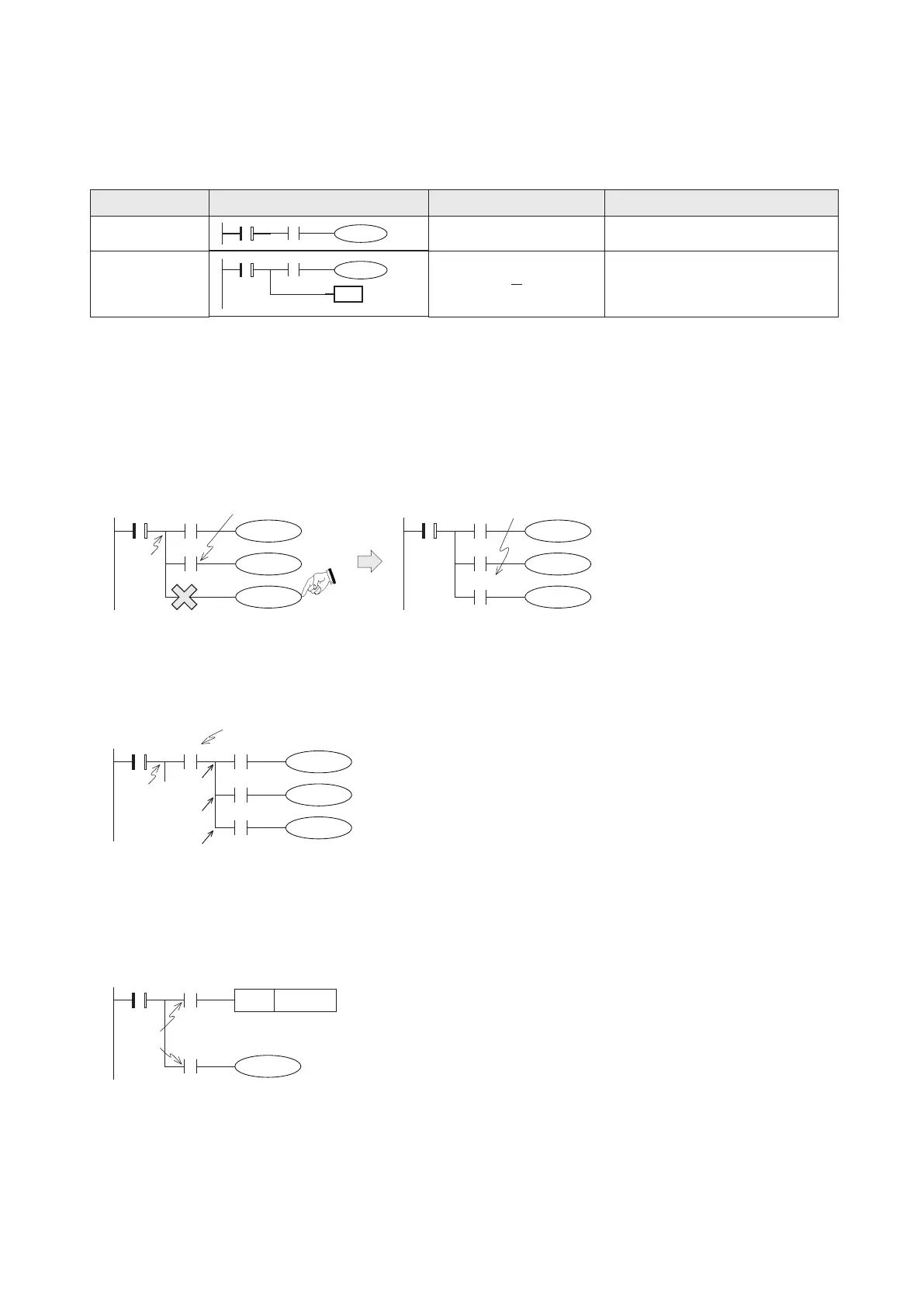
(1) Output Driving Method
As in the left diagram referred below. If inside the Step Ladder has an LD, LDI, LDP or LDF instruction, an output coil can
not directly connected from the inner bus bar of the STL after one of those instructions had been used.
Please change the left diagram into the right one.
Insert a permanently “ON” contact
The permanently “ON” contact
(4) Function of Instruction RET
Since the RET instruction represents the end of a Step Flow the RET instruction will appear eventually after a series of steps.
A program may be written many Step Flows each Step Flow should put an instruction RET at the end. The instruction RET
can be used as many times as required.
(2) Location of Instructions MPS, MRD and MPP
The MPS, MRD and MPP instructions can not be directly used for the STL's inner bus bar, unless an LD, LDI, LDP or LDF
instruction has been used previously.
To drive an immediately following STL step, which typically will have a larger STL
state number than the current step.
To drive a step which is not immediately following or at the separate STL program flow.
(3) Transferring Method of STL
As in the diagram referred below, these two instructions SET S21 and OUT S40 are to drive and transfer to another step.
When the active state is transferred to another step, the previous step itself will be reset to “OFF” automatically.
The difference is that the SET instruction is used to drive an immediately following STL step, but the OUT instruction is used
for to distant jump and drive a step which is not immediately following or at the separate STL program ow.
STL
S
RET
RET
LD X23
Y20
Y21
Y22
The STL's
inner bus
bar
S20 X21
X23
Y20
Y21
Y22
S20 X21
X23
M9000
MPS
MRD
MPP
Y20
Y21
Y22
S20 X21X20
X22
X23
LD X20
Transfer
condition
S40
S20 X20
X21
S21SET
102
4-6 The Relationship Between the SFC and STL
Mnemonic
Staircase chart
Devices Function
The STL's
inner bus
bar