Since a PLC only has 8 high speed inputs X0~X7, once an input point is occupied then it cannot be used for other
high speed functions. Therefore, users should plan carefully in order to make good use of these input points.
Each one of the input points X0~X7 in the VS series PLC can be used for high speed function, such as the high speed
counter, external interrupt or frequency meter. If a X0~X7 is not designed for high speed function, it can still be used as
a general input point.
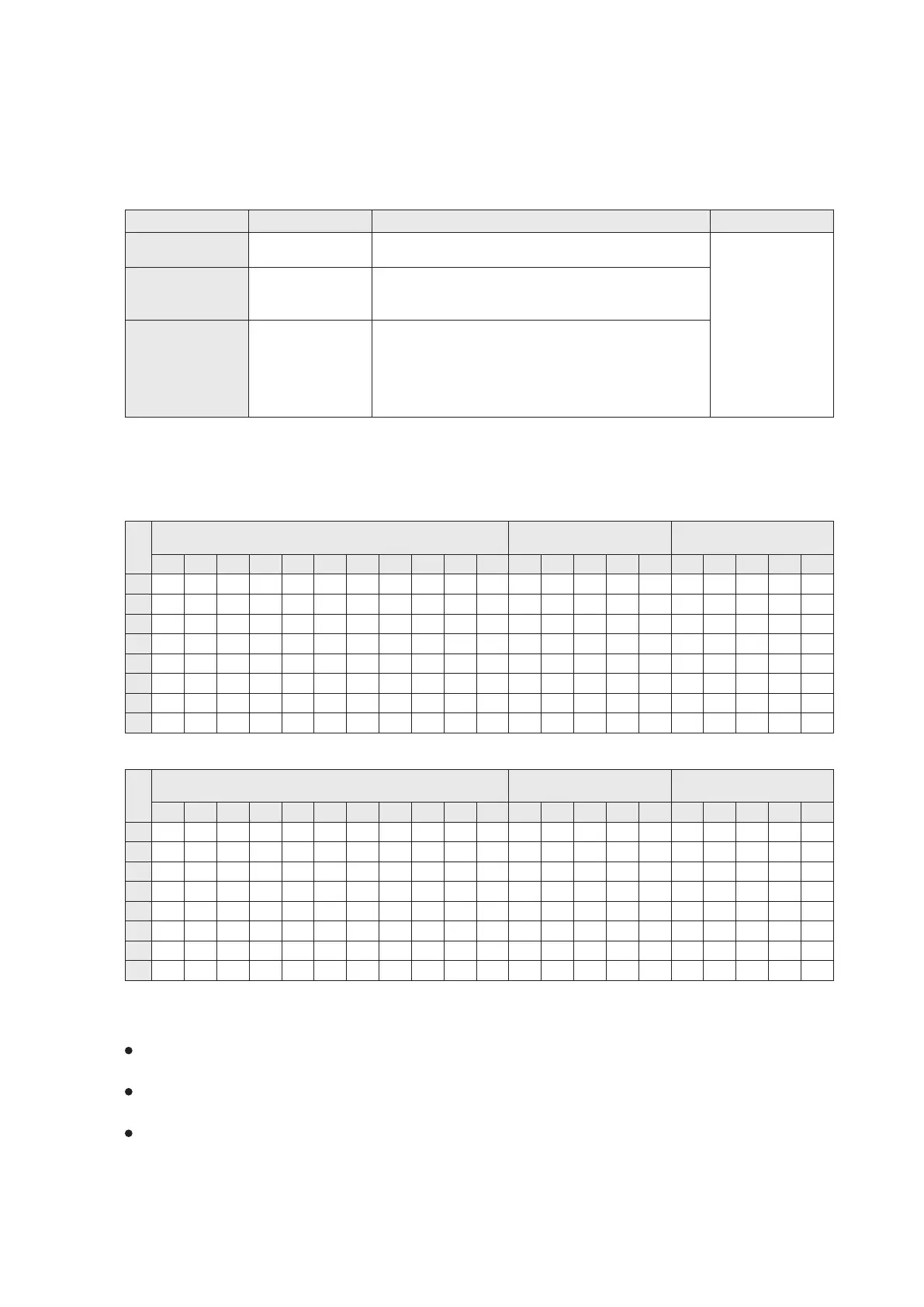
For the purpose of the Software High Speed Counter, it uses the interrupt to receive and count every high speed input
pulse, hence with a “Software” in the front of its name. The counter is a 32-bit Up/Down counter with latched function,
and can be classified into three types. Their characteristics are shown in the table below:
Counter's ID No.
Counter Type Range of Set Value
Count Direction
C235~C245
C246~C250
C251~C255
1-phase
high speed counter
2- phase
high speed counter
A/B phase
high speed counter
Determined by M9235~M9245. OFF is defined as up count while
ON as down count.
The up and down count signals have their own input points.
The direction can be identified from M9246~M9250.
OFF means up counting; ON means down counting.
Determined by the sequence of A/B phase input signals.
Up counting if A-phase signal is ON then B-phase signal turns
from OFF to ON.
Down counting if A-phase signal is ON then B-phase signal turns
from ON to OFF.
The direction can be identified from M9251~M9255.
OFF means Up counting; ON means Down counting.
-2,147,483,648
+2,147,483,647
~
This section only describes the software high speed counters; for planning the PLC program, please refer to other
sections which are regarded more functions of high speed input points.
In Sections 2-7-1~2-7-3, the descriptions of various counters are based on SHSC Mode 1.
U: Count up input; D: Count down input; A: A-phrase input; B: B-phrase input
U/D: Up/Down counting signal input; R: Built-in Reset Input; S: Built-in Start-up input
When input points X0~X7 are applied to perform the Software High Speed Counters (SHSC), there are two operation
modes available. The setting page is at the “Project Parameter Setup” within the programming software.
SHSC Mode 1
1-phase
High Speed Counter
A
B
R
A
B
R
S
S
U/D
U/D
U/D
U/D
U/D
U/D
U/D
U/D
U/D
U/D
U/D
A
B
R
A
B
U
D
R
U
D
R
U
D
R
U
D
U
D
R
A
B
R
R
R
R
R
R
S
S
S
S
2-phase
High Speed Counter
A/B phase
High Speed Counter
Input
X1
X2
X3
X4
X5
X6
X0
X7
C235 C236 C237 C238 C239 C240
C241 C242
C243
C244
C245 C246
C247
C248 C249 C250 C251 C252 C253 C254 C255
A
B
A
B
R
U/D
U/D
U/D
U/D
U/D
U/D
U/D
U/D
U/D
U/D
A
B
A
B
U
D
U
D
R
U
D
U
D
U
D
A
B
R
R
R
C235 C236 C237 C238 C239 C240
C241 C242
C243
C244
C245 C246
C247
C248 C249 C250 C251 C252 C253 C254 C255
U/D
X1
X2
X3
X4
X5
X6
X0
X7
25
2-7 Software High Speed Counter
SHSC Mode 2
Input
1-phase
High Speed Counter
2-phase
High Speed Counter
A/B phase
High Speed Counter