3-7 The SET and RST Instructions
SET
(SET)
Y0
SET
RST
(RESET)
RST
Y0
LD
OUT
LD
SET
LD
RST
X0
Y20
X0
Y21
X1
Y21
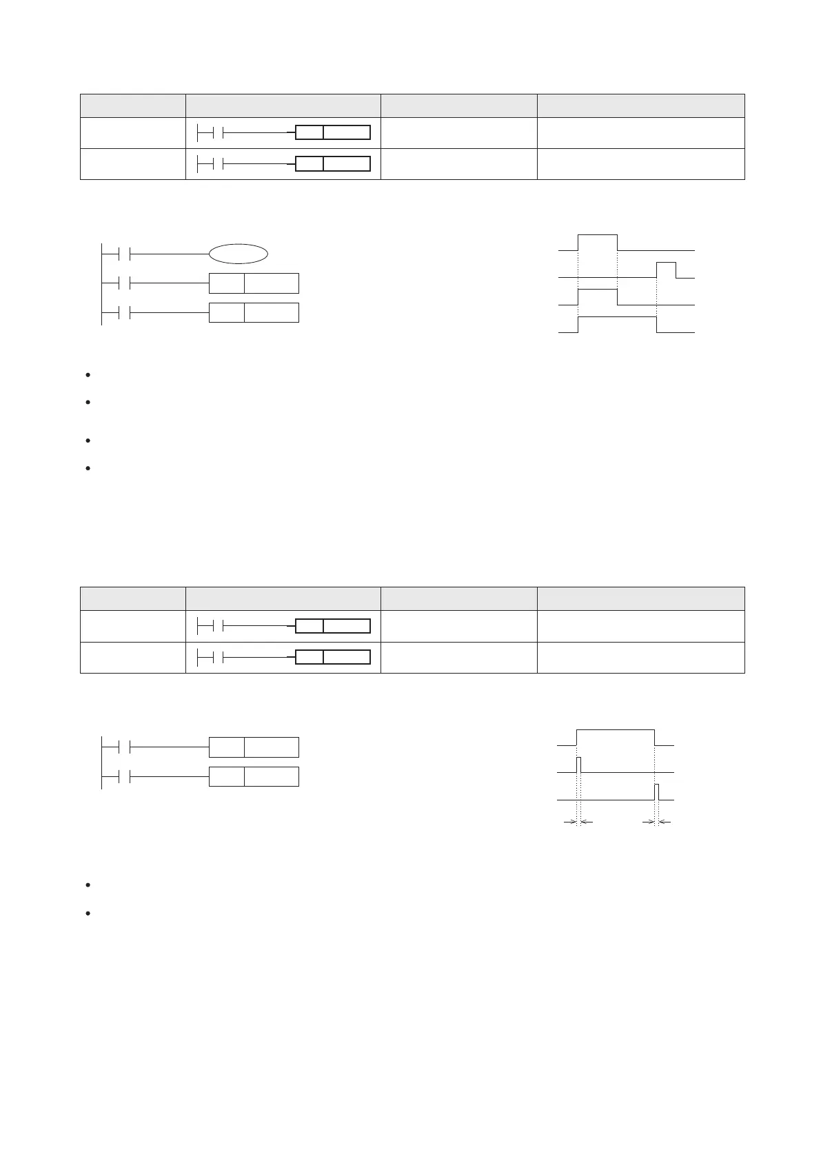
Active I/O duration time sheet
X 0
X 1
Y 2 0
Y 2 1
X0
X1
X0
Y20
SET
RST
Y21
Y21
3-8 The PLS and PLF Instructions
PLF
(PULSE FALLING)
PLS
(PULSE)
Y0
PLS
Y0
PLF
LD
PLS
LD
PLF
X0
M0
X0
M1
X 0
M 0
M 1
X0
X0
PLS
M0
PLF
M1
86
Set component permanently ON
Reset component permanently OFF
Y, M, S, D.b, R.b
Y, M, S, D.b, R.b, T, C, D, R, V, Z
Rising edge pulse
Falling edge pulse
Y, M (Except the Special M)
Y, M (Except the Special M)
Active I/O duration time sheet
The SET instruction sets the output coil permanently “ON” when it has been operated.
The RESET instruction resets the output coil permanently “OFF” or resets the current value of a Timer, Counter or Register
to zero.
The SET instruction and the RESET instruction can use the same output coil, and the number of times is unlimited.
The RST instruction for the device C will have an explicit explanation in the Section 3-9.
One Scan TimeOne Scan Time
When X0=OFF → ON, the M0 will output a pulse for one Scan Time.
When X0=ON → OFF, the M1 will output a pulse for one Scan Time.
Mnemonic Devices Function Format
Mnemonic Devices Function Format
Ladder Diagram
Ladder Diagram
Instruction List
Instruction List