4. Sequential Function Chart (SFC) and Step Ladder (STL)
4-1 What is the Sequential Function Chart (SFC)
4-1-1 The Framework of SFC
In the universe of Automatic Control, the Electro-Control system should work closely with machine movements to get
the result of the Automatic Control, i.e. the synergistic integration technology of Mechatronics, which has become
popular in recent years. However, that is quite a difficult job to learn such a complicated sequential control design for
machinery engineers, therefor the SFC (Sequential Function Chart) is developed accordingly.
The SFC is designed to create an easy way to understand the machine's movements, which has the following features:
4-1-2 Basic Components of SFC
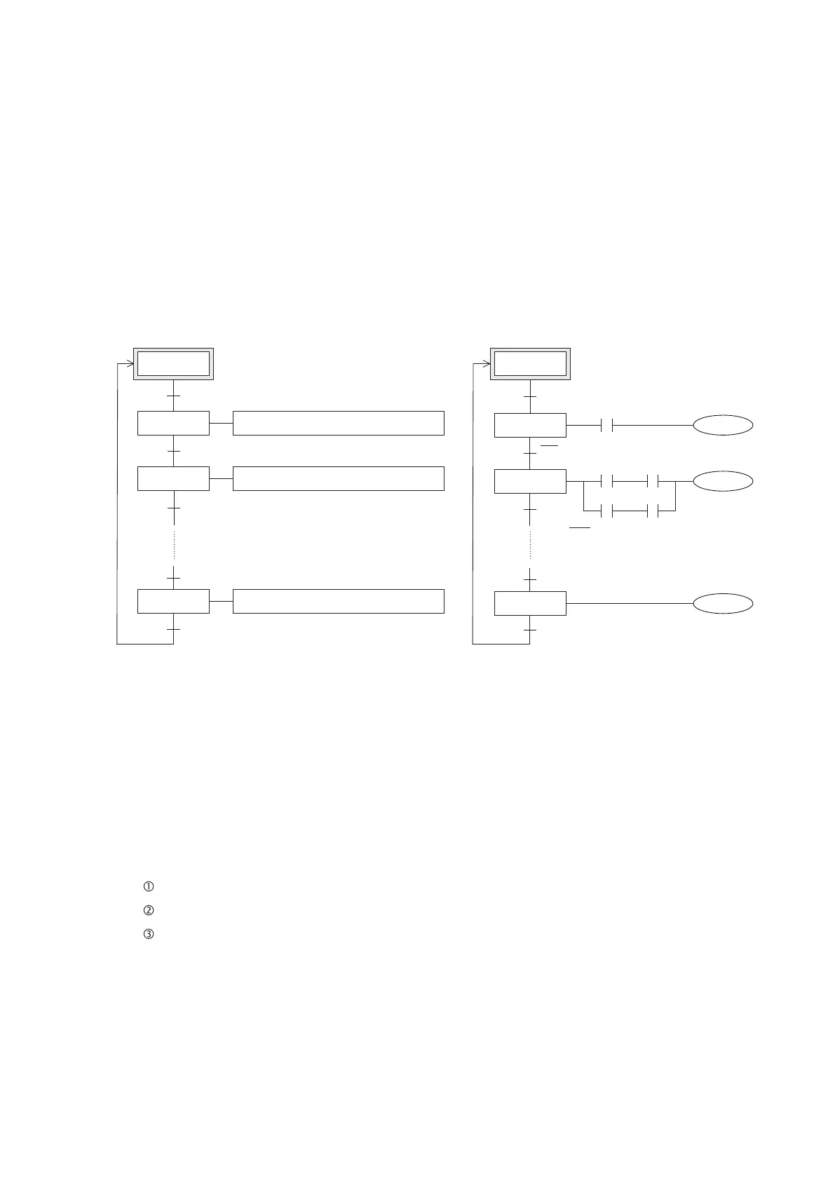
SFC Schematic Diagram
The transfer condition, to control the movement from
the Initial State to State 1
The transfer condition, to control the movement from the
State 1 to State 2
The transfer condition, to control the movement from the
2 to State 3
The transfer condition, to control the movement from the
State (N-1) to State N
The transfer condition, to control the movement
from the State N to Initial State
The Ladder Diagram of Sequential Control
for State 1
The Ladder Diagram of Sequential Control
for State 2
The Ladder Diagram of Sequential Control
for State N
The Actual SFC
X20
X22
X26
X27
X21
X20, X21, X22,… X26, X27
Which are the transfer conditions for each
State.
S0
S20
S21
The left is a Schematic Diagram of SFC and the right diagram is the corresponding actual SFC. The PLC will execute to
start from the Initial State, then complete State 1 → State 2 → … → State N in the sequence based on states' transfer
conditions and achieve a cycle of control.
Initial state
State 1
State 2
State n
S30
91
1. States
(1) Initial State
The rst state to execute after PLC runs. Ordinarily the Initial State is achieved by using the startup initial pulse.
The Initial State is represented by a frame with double sidelines.
(2) Effective State
The Effective State refers to a state which is executive or active during the PLC processing. Under an Effective
State PLC will execute the following actions in sequence:
2. Transfer Condition
There is a line segment to connect between states, and on the line segment put a perpendicular short line which is
used to express the related condition driving the states transfer.
(1) It is not necessary to design the special sequence for stepladders of which state constantly changes, the PLC will
automatically execute interlocks and double coils under different states. Only need to simply design the sequence
function of every state.
(2) Even a person who is not a machine designer can easily learn all actions and conduct jobs such as trials,
adjustment, debug and maintenance.
Driving the coil of the output point, timer or counter relative to the state.
Resetting the last pasted action, i.e. turning the actions which are relative to the last state into “OFF”.
Transferring the machine action to the next state when the transfer condition is authorized. In generally there is
a connecting line to connect the states, and it indicates the direction of the signal.