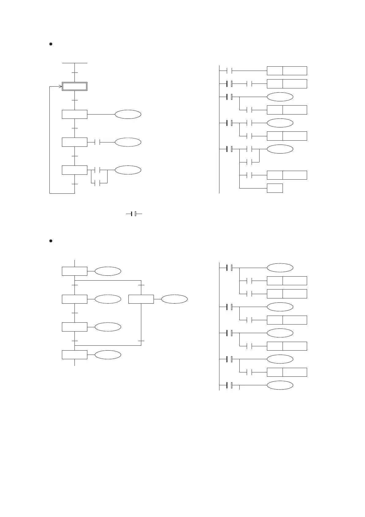
4-6-2 Compare the Descriptive Methods Between the SFC and STL
Selective Branch / Merge at the SFC and STL
(a)SFC
(b)STL
M9002
X0
X1
X2
X3
X24
X26
Y22
Y0
Y21
M100
S0
S20
S21
S22
In diagram (a) SFC, each step has three functions and parts: to drive the output points for loaders to appoint transfer
destination devices and to assign the transition conditions. Such the left SFC by the format of STL is displayed as in
diagram (b), in which we adopt as the symbol for use of STL instructions. And those STL instructions are
provided with the state transfer and auto reset functions.
S20
S21
S22
S0
X1
X2
X26
X3
M100
X24
X0
SET
SET
S21
S22
SET
RET
S0
SET S0
SET S20
M9002
Y0
Y21
Y22
X0
X1
X2
Y22
Y20
Y21
S20
S24S21
S22
S23
Y23
X3
Y24
X4
S20
S21
X0
X3
X1
SET
SET
SET
S21
S24
S22
Y20
Y21
S22
X2
SET S23
Y22
S24
S23
X4
SET S23
Y24
Y23
Simple Flow at the SFC and STL
103
(a)SFC
(b)STL