The Index Registers can be used to modify the operand in an application instruction, the modifiable components are
shown below:
Bit component: X, Y, M, S
Pointer: P, Q (P as the label name of the jump or subroutine cannot be modified)
Word component: The present value of T and C
Index register D, R
The KnX, KnY, KnM, KnS which is composed by X, Y, M, S (Kn itself can not be modified)
The UnG at the part of G (Un itself can not be modified)
Constant: K, H
When using the index register in a 32-bit application instruction, be sure to use paired V, Z registers. At this point, pay
special attention to whether there is residual value in the upper register V. To be safe, use the DMOV instruction when
placing value into the V, Z paired registers.
Here provide some examples that Index registers V, Z are used to modify operands:
① 16-bit instructions, when Z0=4,
Y27Z0=Y33 (The Y is named by octal
number system)
T5Z0=T9
D0Z0=D4
K4M8Z0=K4M12
U1G0Z0=U1G4
②
32-bit instructions(will occupyV,Zregisters), when (V1, Z1)=8,
X20Z1=X30 (The X is named by octal number system)
M0Z1=M8
D0Z1=D8
K8M40Z1=K8M48
R10Z1=R18
MOV K10 Z0
X0
X0
M9000
MOV K0 Z0
When X0=OFF, Z0=0
Using index register in a subrountine
CALL ARITHMETIC
FEND
ARITHMETIC
When X0=ON, Z0=10
˙˙˙˙˙˙˙˙˙˙
Call the “ARITHMETIC” subroutine
The pointer label of the subroutine which is named “ARITHMETIC”
SRET
When Z0=0, operates (D0+D1)×D2→(D4,D3)
When Z0=10, operates (D10+D11)×D12→(D14,D13)
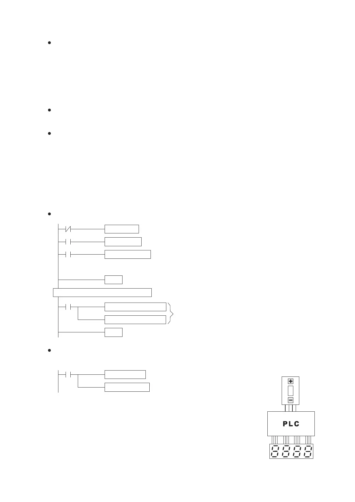
Using thumbwheel switch
to select a Timer to display
Display the present value
of selected Timer
2
X23 〜 X20
Y37 〜 Y20
With the following program and external wiring, you can use the coded inputs to change the value of Z0. Then, can
select one of the present values in T0~T9 and display the number in the external seven-segment display.
Convert the present value of T0Z0
(one of the selected T0~T9) to the
BCD code and send to Y20~Y37,
then via the external seven-segment
display to show the value.
M9000
ADD D0Z0 D1Z0 D3Z0
MUL D3Z0 D2Z0 D3Z0
Inputs X20~X23 are from the thumbwheel switch,
then the instruction converts these inputs to a BIN
value and sends to the Z0, thus Z0 = 0~9.
BI N K1X20 Z0
BCD T0Z0 K4Y20
M9000
33
2-9-2 Using Index Register in Application Instruction
2-9-3 Demonstration Program Using Index Register