M9047
M9040
■
M9046
4-5 STL / SFC Relevant Special Components
In the tables below, the symbol “■” represents that the component is not allowed to use an instruction in the program
to drive the relay or write data to the register.
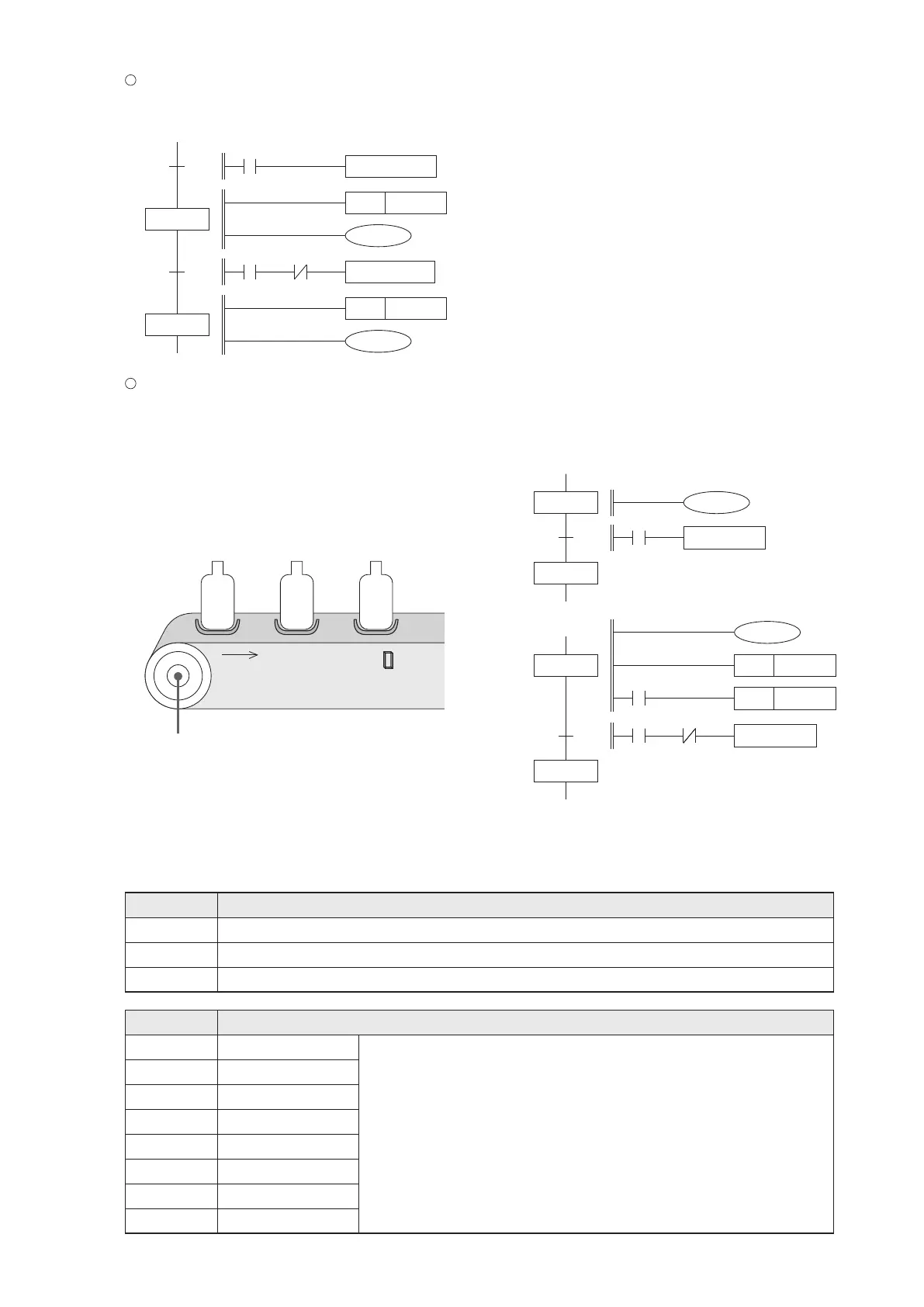
When a signal is repeatedly used to transfer state at different steps, this signal must be a pulse signal. Also, since
the effective state transferring between two sequential steps will cause both of the states ON for a scan time,
therefore the prohibitive M1 signal should be added as shown below. That could avoid transferring from S100 to
S101 immediately.
19
S100
S101
PLS
M1
M0
TRA N S1 00
M0 M1
TRA N S1 01
PLS
M2
In the example of the following gure, when the state of S100 is changed from OFF to ON, it is expected that the Y1
motor rotates to drive the conveyor to move the “Bottle 2” to the position of bottle inspector X1.
When the S100 changes from OFF to ON and the X1 has been turned ON already by the “Bottle 1”, at the Fig. 1 that
will cause the state of S100 transfers to S101 immediately, thus the Y1 turned OFF at once. Therefore, it is necessary
to improve the SFC become the Fig. 2 in order to successfully achieve the purpose. This kind of application is
common in the automatic control, the user must understand the principle of its movements.
20
Conveyor motor Y1
Fig.1
S100
S101
Y1
X1
TRAN S101
Bottle inspector X1
Bottle 3
■
D9041
■
D9042
■
D9043
■
D9044
■
D9045
■
D9046
■
D9047
■
D9040
S100
S101
M0
M1
TRAN S101
Y1
PLS
M1
PLS
M0
X1
101
Bottle 2
Bottle 1
Fig.2
STL monitoring is enable. D9040~D9047 will be active only when M9047=“ON”.
To prevent the step transfer. When M9040=“ON”, the STL state transfer function is disabled.
STL step is working. When M9047=“ON” and any relay of S0~S899=“ON” than M9046=“ON”.
When M9047=“ON”, the active STL step ID numbers will be stored in
D9040~D9047, where the D9040 will be stored the lowest ID number,
the second lowest one will be stored in D9041 and so forth.
st
1 active STL step
nd
2 active STL step
rd
3 active STL step
th
4 active STL step
th
5 active STL step
th
6 active STL step
th
7 active STL step
th
8 active STL step
Register ID No.
Relay ID No.
Description
Description