Two non sequential steps can share a timer with the same ID number. Also, it can be set with different set values
respectively.
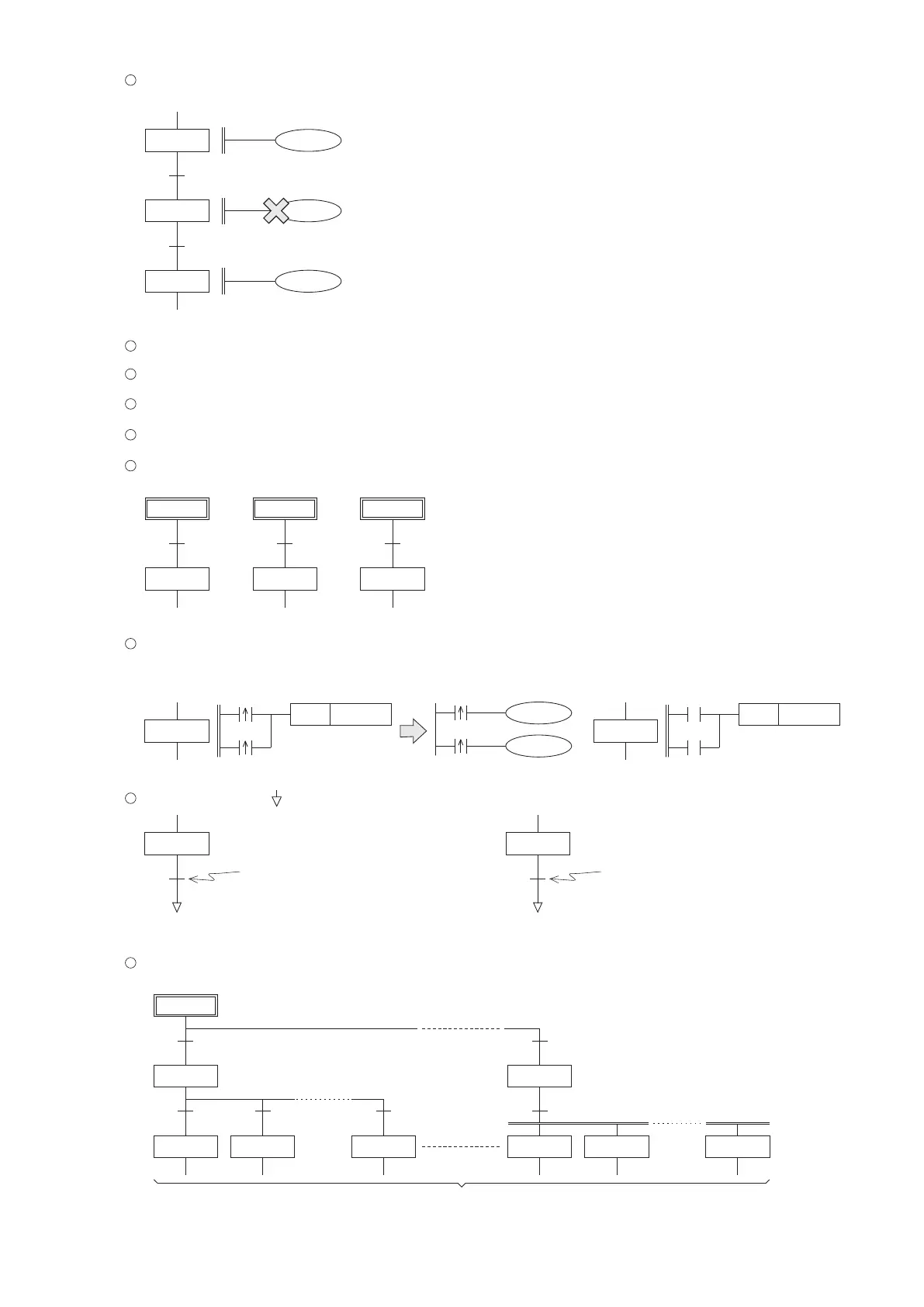
S10
S12
S11
T0
K100
T0
K5
D0
T0
Steps S10 and S11 are sequentially connected, the left side T0 is not allowed.
Steps S10 and S12 are not sequentially connected, the left side T0 is allowed.
The MC and MCR instructions cannot be used in the SFC.
The SET, RST and OUT instructions cannot be used to do the state transfer in the SFC.
The same step relay ID number cannot be used repeatedly in the SFC.
10
When designing a SFC, the ID numbers of used step relays do not need to follow through a specic sequence.
11
12
In the SFC, the S0~S9 are the main initial step relays. However, a general step relay can also be used as an initial
step relay, at the beginning of a SFC ow.
13
14
Avoid using the pulse of rising/falling edge in a SFC. If necessary, can transfer the edge pulse to an auxiliary relay M
in the ladder diagram rst.
15
S10
X0
X1
SET
Y0
S10
M0
M1
SET
Y0
SFC
Expanded view of the SFC
X0
X1
M0
M1
In the ladder diagram
In the SFC, the sign “ ” represents the RESET instruction.
17
S20
S20
If the transfer condition is ON,
then RESET the S20.
S20
S30
For a selective or simultaneously parallel branch, the maximum limit is 8 branch ows.
If using the Ladder Master S to compose a SFC, one SFC diagram can have at most 32 columns.
18
S5
1 2
8
Up to 8 branch ows
Up to 8 branch ows
S0 S10 S100
S10 S100 S500
16
Max. 32 columns
100
If the transfer condition is ON, the
RESET is effected to the S30. Hence,
will not do status transfer (the S20 is
still ON).