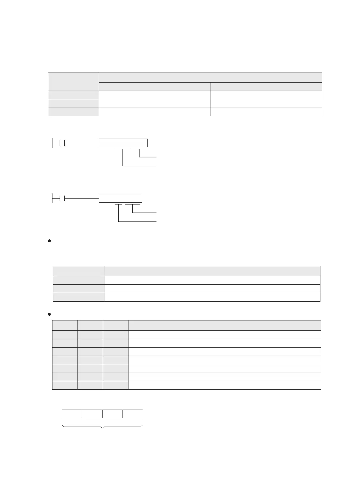
The instruction diagram below will move the content value from the EC1D0 of special card to the register D100 of PLC.
(that card is installed at the EC1 socket)
M9000
MOV EC1D0 D100
The register D100 of the PLC
The EC1D0 of the SF card that is installed at the EC1 socket
The instruction diagram below will move the content value from the register D0 of PLC to the EC2D5 of special card.
(that card is installed at the EC2 socket)
M9000
MOV D0 EC2D5
The EC2D5 of the SF card that is installed at the EC2 socket
The register D0 of the PLC
For convenience, every EC1~EC3 expansion card socket at a VS series PLC will possess 20 special registers that is the
working area of the installed expansion card. When a special card is installed in the socket, the PLC can access related
data for the respective device on the card through its working area.
For easy memorize and convenient application, every special register of each Special Expansion Card is given a
“Simple Code”. The “Simple Code” will be used in the following documents.
The VS-3AV-EC can ONLY be installed at the EC2 expansion socket otherwise it is ineffective. Also, to access this
expansion card is through 3 specific special registers below that instead of expansion card working area.
■
Represents that component is read only.
D9032
■
D9030
■
D9031
Special Register related to the VS-3AV-EC (For this card the Simple Code EC2Dn are useless)
EC3
EC1 EC2
EC1D0
EC1D1
EC1D2
EC1D3
EC1D4
EC2D0
EC2D1
EC2D2
EC2D3
EC2D4
EC3D0
EC3D1
EC3D2
EC3D3
EC3D4
EC1D18
EC1D19
EC2D18 EC3D18
EC2D19 EC3D19
65
Register ID No.
Description
The AD converted value of VI1 at the VS-3AV-EC, 0~10V = 0~4000
The AD converted value of VI2 at the VS-3AV-EC, 0~10V = 0~4000
The DA digital input value for the VO at the VS-3AV-EC, 0~1000 = 0~10V
EC Card Register (Simple Code) related to the VS-4AD-EC
Component Description
To assign the analog input modes of AI1~AI4.
Converted digital value of AI1, 0~4000 or 0~3200.
Converted digital value of AI2, 0~4000 or 0~3200.
Converted digital value of AI3, 0~4000 or 0~3200.
Converted digital value of AI4, 0~4000 or 0~3200.
Identication code: K101 (If code = K240, means connecting error between Main Unit and card)
The version number of this card. (the content value XX indicates Ver. X.X)
To appoint the modes of analog inputs: (the sliding switch should also consistent with the modes)
Nibble #4
Nibble #3
Nibble #2 Nibble #1
b15
b0
AI2 AI1
If the nibble = 0, the channel is assigned for (0~10V) voltage input.
If the nibble = 1, the channel is assigned for (4~20mA) current input.
If the nibble = 2, the channel is assigned for (0~20mA) current input.
If the nibble is any number other than 0, 1 or 2, the channel is disabled.
Example: If VS- 4AD- EC is installed in EC1, and EC1D0 is set to be H3210, then
AI1: voltage input (0~10V) AI2: current input (4~20mA) AI3: current input (0~20mA) AI4: disabled
AI4 AI3
To assign input modes:
2-16-3 The Special Function Expansion Card Related Components
Expansion Card Working Area
EC1
EC2
EC3
D9260 〜 D9279
D9280 〜 D9299
D9300 〜 D9319
Special Register
EC1D0 〜 EC1D19
EC2D0 〜 EC2D19
EC3D0 〜 EC3D19
Expansion Card
Socket
Simple Code