EC3
EC1 EC2
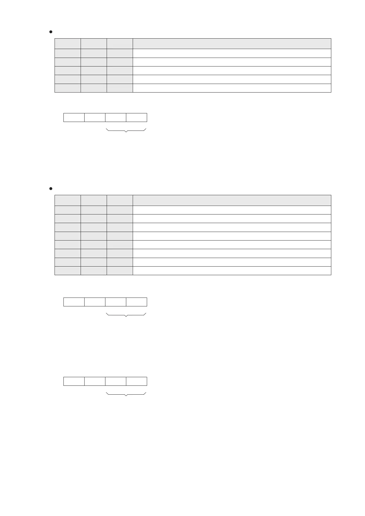
EC1D10
EC1D11
EC1D12
EC2D10
EC2D11
EC2D12
EC3D10
EC3D11
EC3D12
EC1D18
EC1D19
EC2D18 EC3D18
EC2D19 EC3D19
EC3
EC1 EC2
EC1D0
EC1D1
EC1D2
EC2D0
EC2D1
EC2D2
EC3D0
EC3D1
EC3D2
EC1D18
EC1D19
EC2D18 EC3D18
EC2D19 EC3D19
EC1D10
EC1D11
EC1D12
EC2D10
EC2D11
EC2D12
EC3D10
EC3D11
EC3D12
66
The version number of this card. (the content value XX indicates Ver. X.X)
EC Card Register (Simple Code) Related to the VS-2DA-EC
Component Description
To assign the analog output modes of AO1~AO2.
Digital set value for AO1, 0~4000 or 0~3200.
Digital set value for AO2, 0~4000 or 0~3200.
Identication code: K102 (If code = K240, means connecting error between Main Unit and card)
To appoint the modes of analog outputs:
b15 b0
Null
To assign
output modes:
AO2 AO1
If the nibble = 0, the channel is assigned for (0~10V) voltage output.
If the nibble = 1, the channel is assigned for (4~20mA) current output.
If the nibble = 2, the channel is assigned for (0~20mA) current output.
If the nibble is any number other than 0, 1 or 2, the channel is disabled.
Example: If a VS-2DA-EC is installed at the EC1, and its EC1D10 is set to be H10, then
AO1: voltage output (0~10V) AO2: current output (4~20mA)
Nibble #4
Nibble #3
Nibble #2 Nibble #1
Null
EC Card Register (Simple Code) related to the VS-4A-EC
Component Description
To assign the input modes of AI1~AI2.
Read value of AI1, 0~4000 or 0~3200.
Read value of AI2, 0~4000 or 0~3200.
To assign the output modes of AO1~AO2.
Write value of AO1, 0~4000 or 0~3200.
Write value of AO2, 0~4000 or 0~3200.
Identication code: K103 (If code = K240, means connecting error between Main Unit and card)
The version number of this card. (the content value XX indicates Ver. X.X)
If the nibble = 0, the channel is assigned for (0~10V) voltage input.
If the nibble = 1, the channel is assigned for (4~20mA) current input.
If the nibble = 2, the channel is assigned for (0~20mA) current input.
If the nibble is any number other than 0, 1 or 2, the channel is disabled.
To appoint the modes of analog inputs: (the sliding switch should also consistent with the modes)
b15 b0
Null
AI2 AI1
Example: If a VS-4A-EC is installed at the EC1, and its EC1D0 is set to be H10, then
Nibble #4
Nibble #3
Nibble #2 Nibble #1
Null
AI1: voltage input (0~10V) AI2: current input (4~20mA)
To assign input modes:
To appoint the modes of analog inputs:
b15 b0
Null
To assign output modes:
AO2 AO1
If the nibble = 0, the channel is assigned for (0~10V) voltage output.
If the nibble = 1, the channel is assigned for (4~20mA) current output.
If the nibble = 2, the channel is assigned for (0~20mA) current output.
If the nibble is any number other than 0, 1 or 2, the channel is disabled.
Example: If VS-4A-EC is installed in EC1, and EC1D10 is set to be H10, then
AO1: voltage output (0~10V) AO2: current output (4~20mA)
Null
Nibble #4
Nibble #3
Nibble #2 Nibble #1