The identification numbers of the External Input/Output points are assigned by the octal numeral system.
The table below lists the assigned numbers of Input (X) and Output (Y) in the VS1 Main Unit:
Y0~Y3
4 Pt.
Y0~Y5
Pt.6
Y0~Y7
Pt.8
Y0~Y11
Pt.10
Y0~Y 31
Pt.12
Y0~Y 31
Pt.12
Y0~Y17
Pt.16
VS1-10M VS1-14M VS1-20M VS1-24M VS1-28M VS1-32M VS1-32MT-DI
X0~X5
6 Pt.
X0~X7
Pt.8
X0~X13
12 Pt.
X0~X 51
Pt.14
X0~X17
6 Pt.1
X0~X23
Pt.20
X0~X17
6 Pt.1
Models
Input No.
Output No.
The table below lists the assigned numbers of Input (X) and Output (Y) in the VS2 Main Unit:
Y0~Y13
Pt.12
Y0~Y17
Pt.16
VS2-24M VS2-32M
X0~X13
12 Pt.
X0~X17
16 Pt.
Y0~Y17
Pt.16
VS2-32MT-DI
X0 X~ 17
61 Pt.
The table below lists the assigned numbers of Input (X) and Output (Y) in the VSM Main Unit:
Y0~Y5
Pt.6
Y0~Y13
Pt.12
Y0~Y17
Pt.16
VSM-14MT-D VSM-24MT-D VSM-32MT-D VSM-32MT-DI VSM-28ML-D
X0~X7
8 Pt.
X0~X13
12 Pt.
X0~X17
16 Pt.
X0~X17
16 Pt.
Y0~Y17
Pt.16
X0~X17
16 Pt.
Y0~Y13
Pt.12
The table below lists the assigned numbers of Input (X) and Output (Y) in the VS3 Main Unit:
VS3-32M VS3-32MT-DI
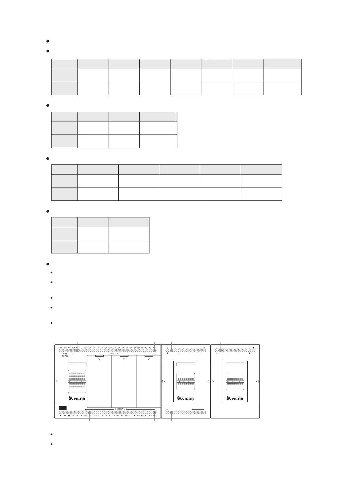
Notes for the VS1 Series PLC Module Expansion
The Main Unit of VS1-10M/VS1-14M/VS1-20M/VS1-24M is not equipped with the module expansion slot.
The Main Unit of VS1-28M/VS1-32M is equipped with the module expansion slot, which can reach 64 inputs and 64
outputs (X0~X77, Y0~Y77), 128 points in total.
The module expansion slot of the VS1 series PLC can be equipped with DIO modules, but not allow special module.
The Main Unit of VS1-28M/VS1-32MT-DI occupies the assigned numbers of X0~X17 and Y0~Y17. Therefore, the
first expansion module is started from X20 and Y20.
The Main Unit of VS1-32M occupies the assigned numbers of X0~X27 and Y0~Y17. Therefore, the first expansion
module is started from X30 and Y20.
The VS-8XY module occupies 8 input points and 8 output points.
The VS-28XYR expansion module will occupy 16 input and 16 output points. Besides, it is unable to expand any
module on its right side.
VS1-32MR
X0 1 2
3 4
5
6 7
10
21 22
23
RUN
ERR
Y0 1 2
3 4
5
6 7
10
11 12
13
PWR
20
11 12
13
14
15 16
17
VS-16XYR
C0
Y0
Y1 Y2
Y3
C1
Y6
Y7
X7
X6X5
X4
X3
X2X1
X0
S S
X0 1 2
3 4
5
6 7
Y0 1 2
3 4
5
6 7
PWR
INPUT X
OUTPUT Y
Y4
Y5
X7
X6X5
X4
X3
X2X1
X0
S S
X0 1 2
3 4
5
6 7
PWR
INPUT X
VS-8X
X0 X23 X30 X40
Y0 Y13
Y20
DC24V
INPUT
16
2-2-3 External Input/Output Assigned Numbers
Models
Models
Models
Input No.
Output No.
Input No.
Output No.
Input No.
Output No.
Y0~Y17
Pt.16
X0~X17
16 Pt.
Y0~Y17
Pt.16
X0~X17
16 Pt.