The PLC's output endpoint is a window for PLC to send out the computed results, and is used to interface with a variety
of loads. Since the output signals are to drive external loads and to complete machine's actions, must pay extra
attention about the safety. Please note the following points:
Y0
X1
Y1
X0
X2
Y0
Y1
X1 X2
X2
X0
X0
X1
X0
Y0
X1
Y1
Y0
X0
X1
Y1
Y0
X0
X1
Y0
X0
X1
5
1-1-5 PLC Output Signals
1. Never ignore the possibility of the PLC failure. It is required to design an external safety circuit and safety mechanism
to avoid accidents.
2. PLCs typically push external loads through relays or transistors. The difference between the characteristics of two is
great, with each advantages and disadvantages. In designing, one should select properly.
The advantages of using a relay are that its contact switch has no current polarity and promotes more current (about
2A), and AC or DC power supply can be used. Its shortcomings are that the contact switch is mechanical, with
mechanical life and electrical life limits. Basically, the relay is not a durable product, and becomes the unreliable
factor in a control system.
The advantages of using a transistor are since it switches by the semiconductor. The number of swap times is
unlimited and the speed of switch is fast, depending on demands could reach hundreds KHz. Its shortcomings are
has current polarity, can only be used for DC load, below 30V and with less current (about 0.1A ~ 0.5A).
When using a relay output, must pay attention to the frequency of action then to calculate the machine's life. That is
for to avoid controller breakdown due to the damage of the relay. Therefore, most control panels take the approach
of attaching a relay externally. Using external relays to promote loads can be considered as the most correct way to
assemble panels. At this point, a transistor output controller can be used to enhance the panel's reliability.
3. In order to prevent interference from noises, the PLC outputs must take isolation measures. The relay output is
magnetically isolated and this can cause an output delay of about 10 ms. The transistor output is isolated by a
photocoupler, the output delay is below 1ms for the general output but only several µs delay for high-speed output.
4. There is a specication of output capability for the load and should be taken seriously. Do not use excessively. In
general, the output specication of the relay is AC220V 2A or less; the transistor is DC30V 0.1A ~ 0.5A or less. For
the unsuitable load to push excessive output at a short time may not have a problem. However, it will certainly affect
the service life of PLC.
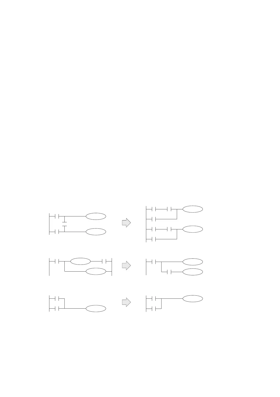
1-1-6 Some Improper Diagrams at a PLC Program
Some conventional circuits of relay switchboards cannot be directly replaced by the Ladder Diagrams at PLC.
The following diagrams indicate such circuit loops on the left and the alternative for PLC are on the right.