5 General Rules of Application Instructions
5-1 The Formats of Application Instructions
W D T
Instruction and Operand
Each application instruction has its unique instruction mnemonic, e.g. ADD, CMP..... , etc.
Some application instructions are purely made up of themselves:
Based on the needs, each application instruction owns different number of Operands. And each application instruction
has different device types. The available types of each Operand device are shown as in the following table:
Most of the application instructions are constituted by instruction themselves and several “Operands”:
Devices for Operand
Instruction
The “ ” in the table above indicates the operand which can be modified by an Index Register V, Z; while the “ ”
means not modifiable.
Operand
m
1
m
2
D
SMOV
S
n
As shown above , , , , are Operands. There are many types of Operand in application instructions,
their symbolic meanings are:
: Source Operand (device). It usually refers to the Operand with unchanged contents after executed.
: Destination Operand (device). It usually refers to the Operand in which instruction execution outcomes are stored.
, : Those Operands used to specify operational constants. But some , of instruction can use
Register D or R to execute indirect specification. , , , ... represent multiple , .
, ...represent multiple source Operands for an instruction.
, ...represent multiple destination Operands for an instruction.
n
S
D
n
S1 S2
D1 D2
S
D
m n
m
m n
n
1
n
2
For programming software such as the Ladder Master S, a space is needed between the instruction and each operand
to separate them.
m
1
m
2
m
1
m
2
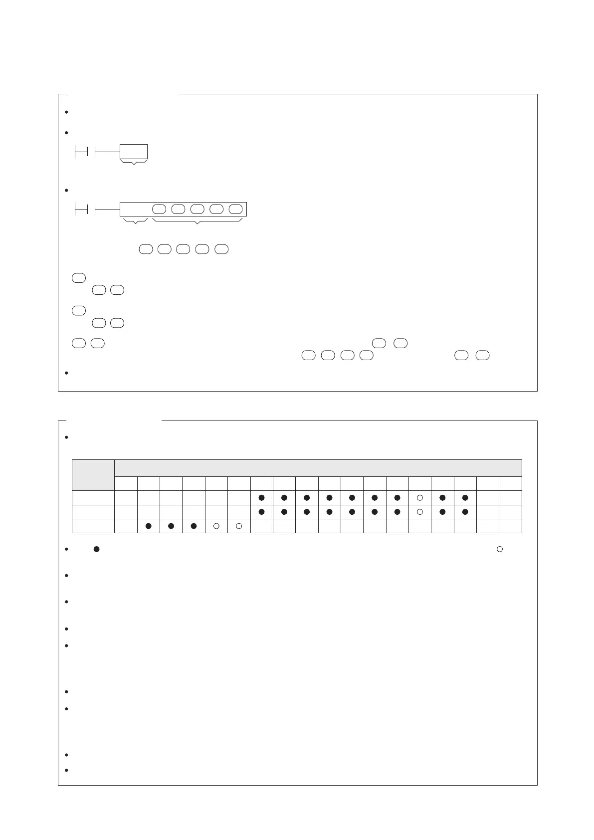
X Y M S KnX KnY KnM KnS T C UnG
" $"
V,Z K,H
E
D.b R.b
D,R
Operand
S1
S2
D
Devices
121
Instruction
In the application instructions, if a D.b, R.b or V, Z is specied as the device of the operand, using V or Z for
modication is prohibited.
After organized, continuous bit devices are displayed as KnX, KnY, KnM, KnS to store data. That “n” behind K is to
represent how many continuous “Nibbles” will be used.
Those T and C in the table above refer the present value registers of Timer (T) and Counter (C).
All of T0~T511, C0~C199, D and R are 16-bit registers. When the instruction species the process of 32-bit data,
two consecutive 16-bit registers will be occupied. For example, if a 32-bit instruction species to use the D100 as its
Operand, then a 32-bit register (which is composed of D101 and D100) will be occupied. While the D101 will assign
to the upper 16 bits and the D100 is the lower 16 bits. The same rule is also applied to the T, C and R.
The UnG in the table refers to the BFM in the special module. For example, U1G3 indicates the operand of this
instruction is specied to the BFM #3 in the special module No. 1. Since the programming software Ladder Master
S at the monitoring mode could not to read the status at the special module's BFM directly, the operand in the
instruction which is appointed to the UnG will not have the correct value to display.
The letter E in the table refers to a real number constant.
The “$” in the table refers to a string that is composed of ASCII code.
The 32-bit Counter (C200~C255) can be used as the Operand of a 32-bit instruction only.