3-6 The MC and MCR Instructions
MC
(MASTER CONTROL)
MCR
(MC RESET)
N0〜 N7
N0〜 N7
MC N0
MCR N0
MC
LD
OUT
LD
OUT
MCR
LD X0
N0
X1
Y20
M10
Y21
N0
If X0=ON then
If X0=OFF then
Y20=OFF
Y21=OFF
X0
X1
M10
MC N0
Y20
Y21
MCR N0
85
Denote the start of a master control block
Denote the end of a master control block
X0
X1
X21
X2
X22
X3
X23
X24
X25
MCR N2
MCR N1
Y26
MCR N0
Y25
MC N1
Y21
MC N2
Y22
MC N3
Y23
MCR N3
Y24
X20
Y20
X26
MC N0
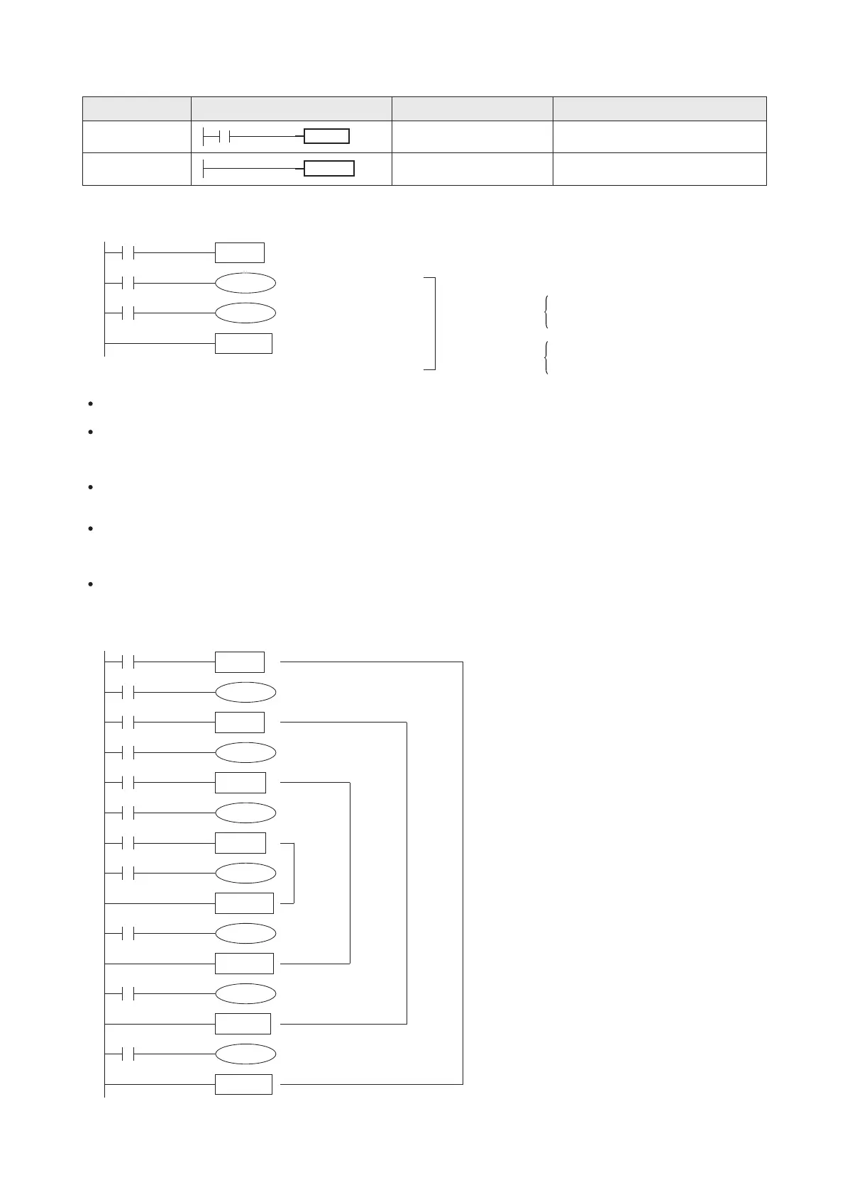
The X0 is the condition contact
Status of Y20 = Status of X1
Status of Y21 = Status of M10
When the condition contact X0 is “ON”, all instructions between the MC and MCR instructions will be executed normally.
When the condition contact X0 is “OFF”, all instructions between the paired MC and MCR instructions will NOT be
executed, also all ordinary Timers and the coils which is driven by the OUT instruction will be reset; but the Retentive
Timers, Counters and the status of coils which is driven by the SET / RST instruction will be kept.
Use the MC instruction to shift the bus line (the Initial logical operation) to a point behind the conditional contact and then
use the paired MCR instruction to return to the original bus line.
A master control block allows to contain another master control block inside, which is to form a nest level. This structure
at the most can have 8 levels N0~N7. The top nest level shall be the N0, and followed by N1, N2..., so the most inner level
shall be the N7.
A program example with a multiple nest levels structure is shown below:
th
4 level
rd
3 level
nd
2 level
st
1 level
Mnemonic Devices Function Format
Ladder Diagram
Instruction List
Ladder Diagram
Become a master control block which is controlled by the
X0.