Double-word device (32 bits)
Word device which is composed of bit devices
5-2 Data Process of Application Instructions
D0,D1,D2,D3 ............
R0,R1,R2,R3 .............
T0,T1,T2 .....................
C0,C1,C2 ....................
............
D0(D1,D0),D2(D3,D2),D4(D5,D4)
.............
R0(R1,R0),R2(R3,R2),R4(R5,R4)
................
T0(T1,T0),T2(T3,T2),T4(T5,T4)
................
C200,C201,C202
............
K1X20,K1X24,K1X30,K1X34
............
K2Y20,K2Y30,K2Y40,K2Y50
.........
K3M0,K3M12,K3M24,K3M36
.............
K4S0,K4S16,K4S32,K4S48
When bit devices are organized as a word device, the header ID number of bit device can be specified as any legally
device. But recommend to specify the Kn X or Kn Y is by the ID number ended with “0”, such as the X0, X20, Y20,
Y30..., while to specify the ID number of the Kn M or Kn S is the multiple of “8”, such as the M0, M8, M16... The
recommendations can improve system efficiency.
When bit devices are organized as a word device, each digit of a hexadecimal word is composed by 4 bit devices
(a Nibble). The Kn portion of the statement identifies the range of devices included. The “n ” can be a number from
the range 1 to 8 and it actual represents 4×n bit devices (n digits hexadecimal word or n Nibbles). Thence, the bit
devices to be used as a word component that number of organized bits is the multiple of 4.
K1M0 refers to a one-digit of hexadecimal word device, that is composed of M0~M3.
K2M0 refers to a two-digit of hexadecimal word device, that is composed of M0~M7.
K4M0 refers to a four-digit of hexadecimal word device, that is composed of M0~M15.
K5M0 refers to a five-digit of hexadecimal word device, that is composed of M0~M19.
K8M0 refers to an eight-digit of hexadecimal word device, that is composed of M0~M31.
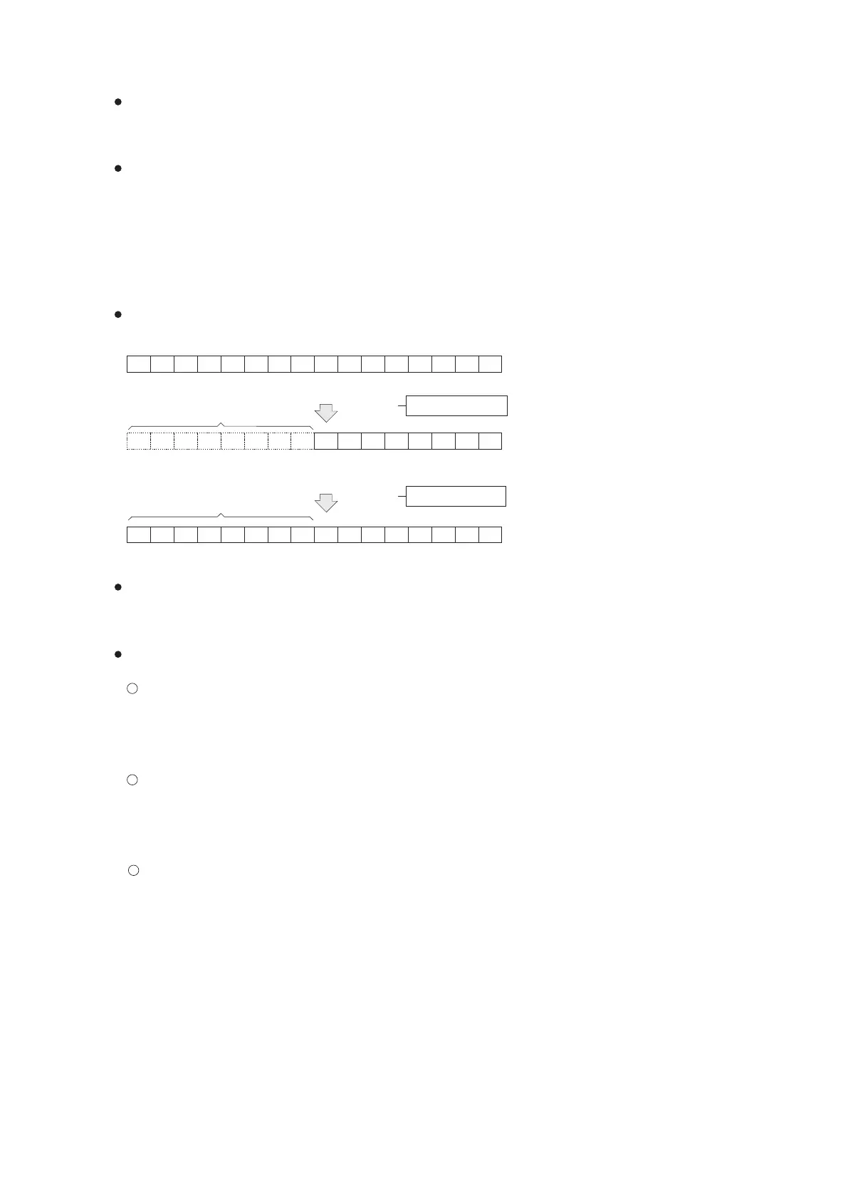
Data transference between registers and word devices which are composed of bit devices, the change should study
up by the example below.
The X, Y, M and S are called bit devices, because they have only two different status (“ON” or “OFF”). But the T, C
D and R are called word devices because they are specially used to store data. Some bit devices can be a group
together as a word device pattern, shown in the form of Kn X, Kn Y, Kn M and Kn S. This organized bits become a word
device, that can be used in an application instruction for storage of data.
The unused bits will not
changed, keep the status
as before
Execution
Added with “0”
MOV D0 K2M0
1
0
1
0
1
0
1
0
K2M0
0 0 0 0 0 0 0 0
1
0
1
0
1
0
1
0
M15 M14 M13 M12 M11 M10 M9 M8 M7 M6 M5 M4 M3 M2 M1 M0
0
1
0
1
0
1
0
1 1
0
1
0
1
0
1
0
b15
b0
b15
b0
D0
MOV K2M0 D1
D1
1
2
3
123
Execution
When the Operand of an application instruction is transformed to several sequential devices, the sequential ID
number at different types are referred as below:
Word device (16 bits)