When X21 is ON, the C246 receives counting signal from either X0 or X1
input point.
When X20 is ON, the RST instruction is executed. C246's present value is
reset to 0, and its output contact becomes OFF.
The C246 2-phase high speed counter which should use the user program
to control the activation and reset processes.
When X21 is ON, C248 is activated to receive the counting signal from
X3 or X4.
When X3 changes from OFF to ON, the present value of C248 increases
by 1.
When X4 changes from OFF to ON, the present value of C248 decreases
by 1.
When X20 is ON, the RST instruction is executed. The C248's present value is reset to “0” and its output contact
becomes OFF. If the application of C248 is not demanded to reset by the program, could ignore this line.
When X5 (the designated built-in reset signal of C248) is ON, the present value of C248 will be reset to “0” and its
contact will become OFF.
The set value of C248 is provided by the content value of D1 and D0.
The C247~C248 at the Mode 1 are 2-phase high speed counters which should use the program to activate then
by the program or built-in reset input to clear.
When the X21 is ON and the X6 (designated start-up input of C249) is
ON, the C249 is activated to receive the counting signal from X0 or X1.
When X0 changes from OFF to ON, the present value of C249 increases
by 1.
When X1 changes from OFF to ON, the present value of C249 decreases
by 1.
When X20 is ON, the RST instruction is executed. The C249's present value is reset to “0” and its output contact
becomes OFF. If the application of C249 is not demanded to reset by the program, could ignore this line.
When X2 (the designated built-in reset signal of C249) is ON, the present value of C249 will be reset to “0” and its
contact will become OFF.
The C249~C250 at the Mode 1 are 2-phase high speed counters which should use the program and start-up
input to activate then by the program or built-in reset input to clear.
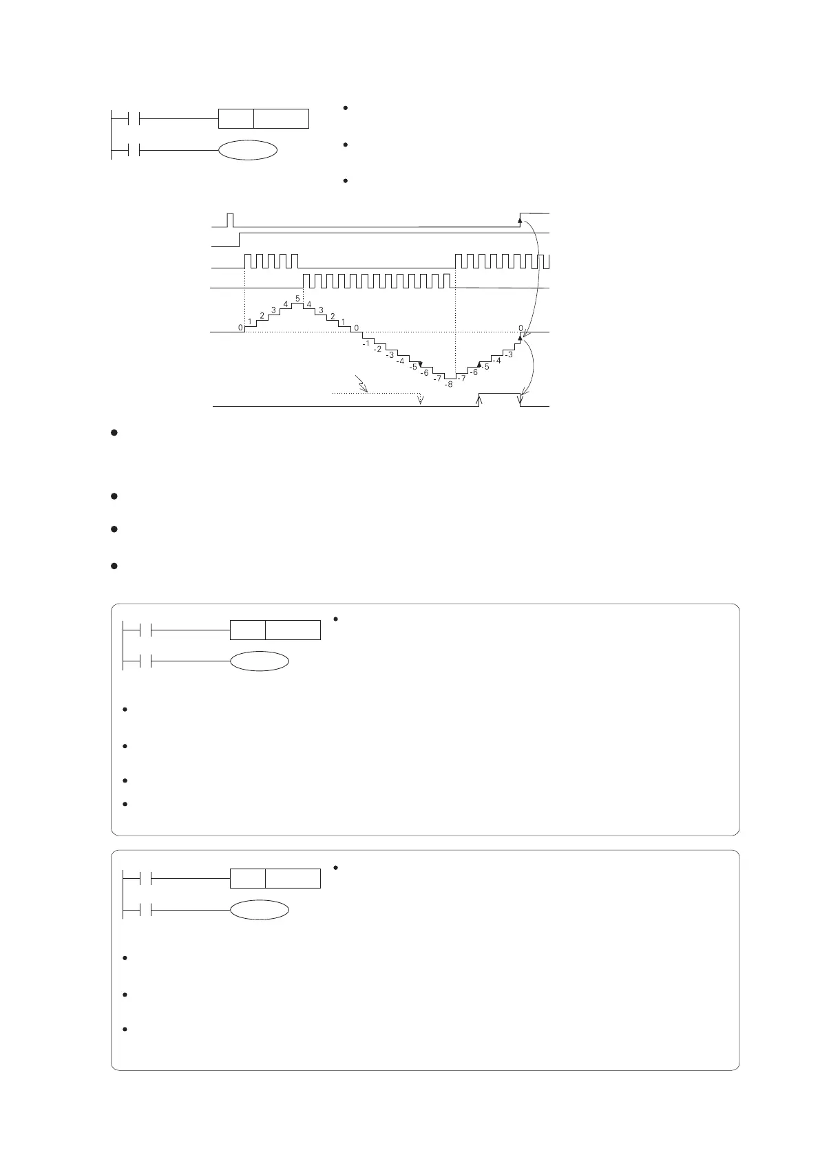
When the start-up signal X21 is ON and there is a pulse entering from either X0 or X1, the present value of C246 will
Up/Down change.
When X0 changes from OFF to ON, the present value of C246 increases by 1.
When X1 changes from OFF to ON, the present value of C246 decreases by 1.
When the present value of the C235 increases from -6 to -5, its output contact switches from OFF to ON. Oppositely,
when the present value of a counter decreases from -5 to -6, its output contact switches from ON to OFF.
If the counter up counts accumulated beyond +2,147,483,647, the present value will automatically change to
-2,147,483,648. Similarly, the down counting below -2,147,483,648 will have the result +2,147,483,647.
The Up/Down counting direction of a 2-Phase High Speed Counter C246~C250 can be watched by to monitor the
M9246~M9250. The related relay OFF means up counting; ON means down counting.
If the output contact was ON
X21
C246
K-5
X20
RST C24 6
X21
C248
D0
X20
RST C 24 8
X21
C249
K100
X20
RST C 24 9
27
2-7-2 2-Phase High Speed Counter
Reset signal X20
Start-up signal X21
Up count signal X0
Down count signal X1
Present value of the C246
Output contact of C246