4-2-2 Convert the Flowchart to the SFC
In an actual application, the external input
signals and output loads must be wired to
the PLC's input and output terminals, therefore
it could receive the state of external signal and
actually drive the load.
In this example, the START button connects to
the input point X0, the output Y0 is for the
READY indicator, the Y1 is for the lighting, the
Y2 is for the valve of surrounding nozzles and
the Y3 is for the valve of central nozzle.
The state of each Step Relay in the program
indicates which SFC procedure is active, and
uses the Transferring Condition under the step
to move the effective status to next Step Relay.
At the system, the General and Latched Step
Relays (S10~S899, S1000~S4095) can be
used without to notice about the order of the
component number, but the S0~S9 are
specially assigned to the Initial State. Besides,
should not reuse the same component number
for the steps.
According to the note above and the I/O
control requirements, could convert the
owchart to the right side SFC program.
Those components T0~T2 are the PLC
built-in timers, the characteristic of this timer
type is up counting by the unit of 0.1 seconds.
S0
S10
S11
S12
S13
Y0
Y3
T2
RST
RST
Y1
Y2
T1
SET
Y2
K100
T0
SET
Y1
K50
Drive the valve of central nozzle.
K200
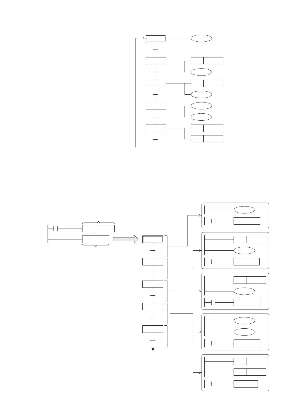
4-2-3 Use the Ladder Master S to Edit the SFC
The programming software Ladder Master S provides the function to construct the SFC. Thus, the SFC at the previous
section can use the Ladder Master S to compose at a computer, then load it to a PLC to test run and debug.
Expand
Expanded view of the
SFC block's structure
S0
S10
S11
S12
S13
S0
The detail action of each single step
M9002
SET S 0
SFC T E ST
Use the Initial State to
activate the following SFC
The Ladder Master S makes use of the
SFC instruction to construct a SFC block
in the program, every block should give
an identication name (up to 16 characters)
after the SFC instruction. Also, the block
can be expanded to edit and view its SFC
structure and detail actions.
Ladder Diagram
X0
Y0
TRA N S1 0
Y3
T2
TRA N S1 3
K200
T2
S13
RST
RST
Y1
Y2
TRA N S0
T1
T1
SET
Y2
K100
TRA N S1 2
Timer T0 is
reached
T0
T0
SET
Y1
K50
TRA N S11
95
Shut the lighting down.
Turn the valves of nozzles
OFF.
Activate the coil of 10 second
timer T1.
Activate the coil of 20 second
timer T2.
Illuminate the lighting.
Activate the coil of 5 second
timer T0.
Drive the valve of
surrounding nozzles.
All actions
are nished
Turn the READY indicator ON at
this standby step.
The START button
Timer T1 is
reached
Timer T2 is
reached
The programming of SFC with the Ladder Master S is illustrated as follows:
Expand
Expand
Expand
Expand
Expand