472
8-4-3 8 Axes Positioning Program Example
One VS series transistor or line driver Main Unit can support 4 axes position control. If the control is required more than
4 axes, one unit is not enough. However, we can use the character of the CPU LINK communication to immediately
transfer data to other PLCs. At the following example, that links two VS series PLCs to perform an 8 axes positioning.
In the same way, to control more axes are available.
The master station #0 is the main PLC to handle the communication procedure and make the positioning command,
the Station No. 1 become the real output PLC to control #5~#8 axes.
There are 3 sections to explame the control system.
Section 1: To plan the components which will be used for the data transfer between PLCs.
At the project of the master Station No. 0 to establish the CPU LINK communication table. The table is to
designate components to send the data from Station No. 0 to 1 and some are about to send data from No. 1
to 0. This example uses the D100~D114 to send the data from Station No. 0 to 1 for the #5 axis, and the
D115~D119 to send the feedback data from Station No. 1 to 0. The list below shows the related
components will be used by the #5~#8 axes.
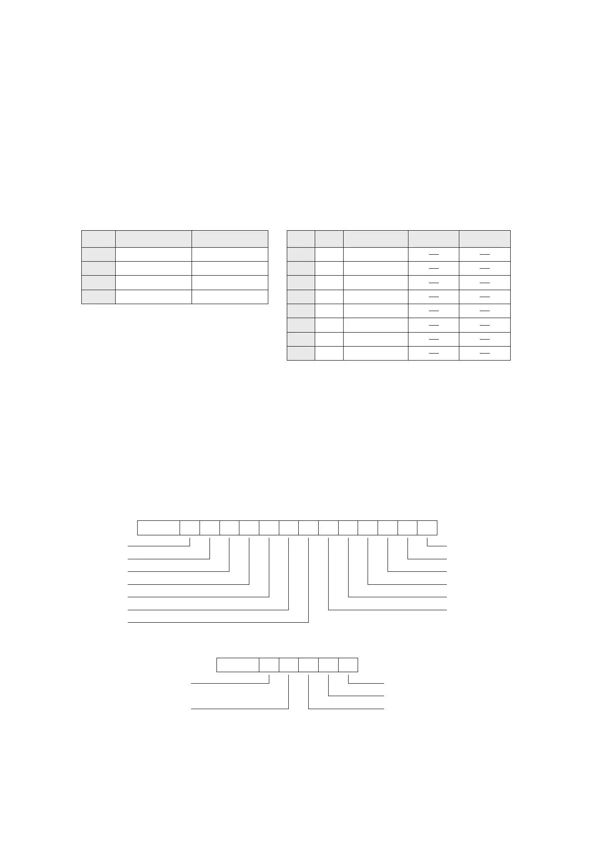
The conguration for #5~#8 axes:
Axis No.
D100~D114 D115~D119
D120~D134 D135~D139
D140~D154 D155~D159
D160~D174 D175~D179
From No. 0 to 1 From No. 1 to 0
#5 axis
#6 axis
#7 axis
#8 axis
By the purposes to establish the communication table “CPUL0”:
1
2
3
4
5
6
7
8
0
0
0
0
D100 – D114
D115 – D119
D120 – D134
D135 – D139
D140 – D154
D155 – D159
D160 – D174
D175 – D179
1
1
1
1
Item
No.
Station
No.
Device Range
Word / Bit
Disable
Contact
(D119, D118) — Current location feedback
D114 — Operation command
D115 — Operation status feedback
b0
b1b2
b3
b4
b5b6
b7
b8b9b10
b11b12
b15~b13
STOP
JOGF
JOGR
ZRN
DRVR
DRVA
PLSV
DVSA
DVSR
DV2I
DVIT
DV2R
DV2A
b0
b1b2
b3
b4
b15~b5
READY/BUSY ag
Pulse output status ag
Zero home positioning
had been completed
Positioning abnormal stop ag Positioning completed ag
(D117, D116) — Current speed feedback
The transfer purposes of related components: (below are for the #5 axis only, the rest may be inferred by analogy)
(D101, D100) — Set JOG speed
(D103, D102) — Set ZRN (Home Positioning) speed
(D105, D104) — Set ZRN (Home Positioning) creep speed
(D107, D106) — Set target position #1
(D109, D108) — Set target position #2
(D111, D110) — Set operation speed #1
(D113, D112) — Set operation speed #2