471
X0
X16
X17
S/S
X14
X15
X12
X13
JOG+
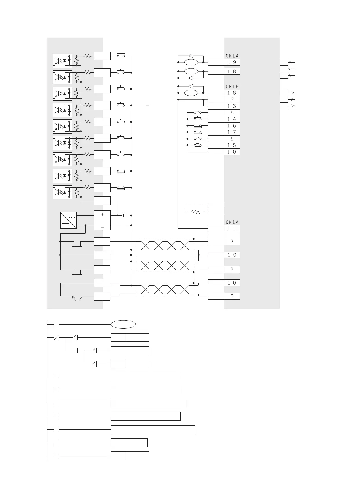
VSM-32MT
X11
Y0
C0
Y1
C1
Y7
24V DC
power
ALM
VDD
COM
SON
RES
LSP
LSN
T L
EMG
S G
P P
S G
S G
N P
C R
MR-J2 series
servo motor drive
RA1
RA2
RA3
RD
INP
P
C
OPC
S D
X10
24V
IN
JOG
Set its parameter Pr0 to
the position control mode
R
S
T
U
V
W
SET
M0
Set the condition contact of the Home Position Return function
DDRVA K0 K100000 Y0 Y1
The function to move back to the zero point
(= home position when the D9346=0)
DZRN K100000 K1000 Y0 Y1
The Home Position Return function
DDRVR K500000 K100000 Y0 Y1
The function of single-speed positioning
ZRST M0 M2
To clear all the function condition contacts when one of those is nished
X10M9340
M9342
X15
M2
M0
JOGF K300 K10000 Y0 Y1
JOGR K300 K10000 Y0 Y1
X11
X12
M1
M9345
SET
Y10
M9343
SET
M2
Set the condition contact of the single-speed positioning
M9344
X13
X14
SET
M1
Set the condition contact for to move back to the zero point
Near point signal
(DOG)
Home position
return
Move back to
zero point
Single-speed
positioning
Stop
Forward limit
switch
Reverse limit
switch
The wiring example between the VSM transistor Main Unit & Mitsubishi servo drive (MR-J2)
3-phase
electric power
Servo motor
SON : Servo ON
RES : Alarm reset
LSP : Forward limit
switch
LSN : Reverse limit
switch
TL : Torque limit
switch
EMG : Emergency stop
Regenerative
resistor
Plate
The JOG+ function
The JOG – function
The positioning function has been stopped abnormally
Prevent the Y0 to generate the pulse string (by gradually slow down)