70
-
VS 4AD
-
VS 2DA
-
VS 3A
-
VS 6A
-
VS 4TC
-
VS 8TC
-
VS 2PT
-
VS 4PT
2-17 Special Function Module
The VS Series PLC offers various Special Function Models, such as analog input/output and temperature input. The
following is the list of selectable special models.
Item
Specifications
Model Name
Special
Function
Module
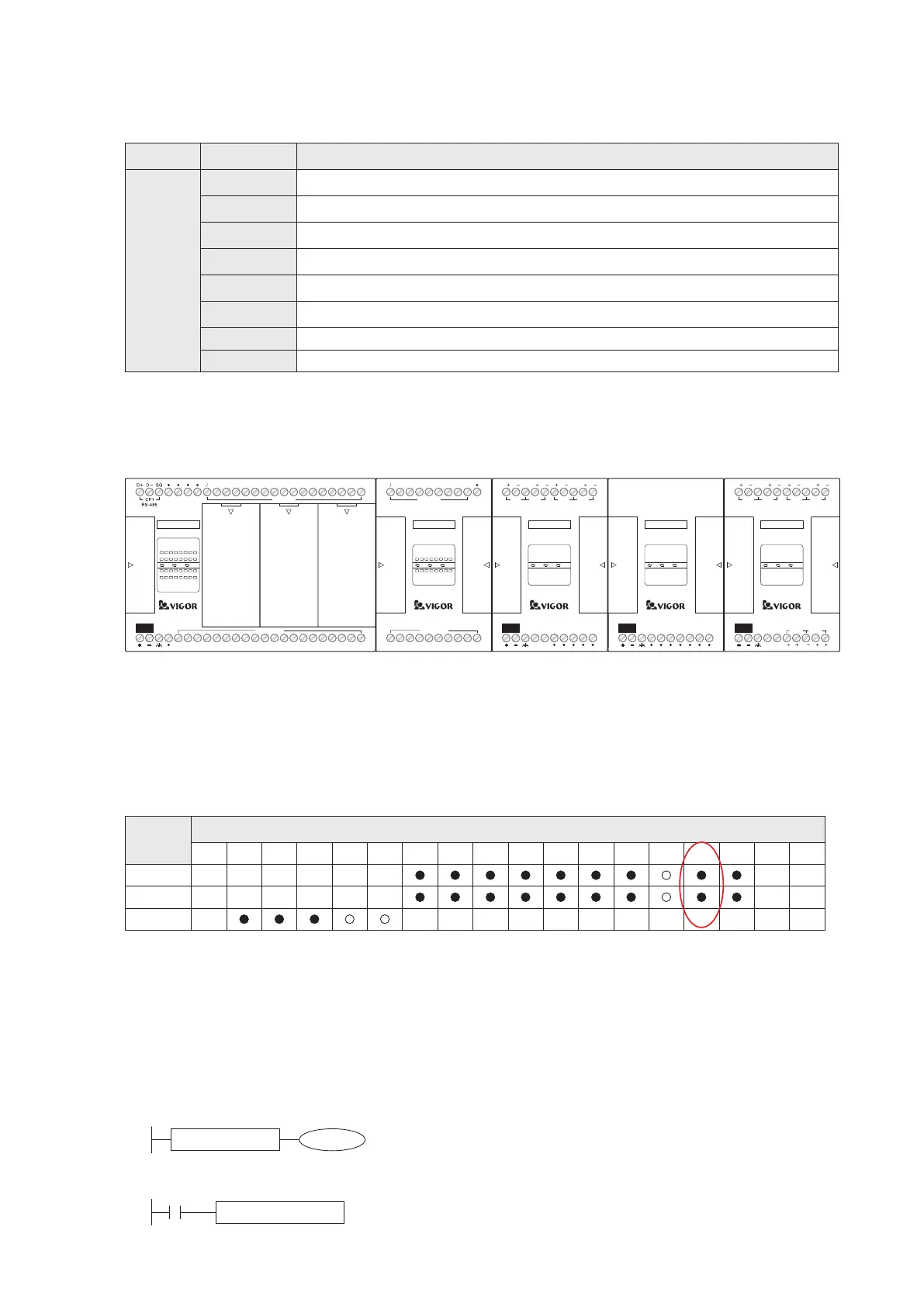
All the Special and DIO Expansion Modules are serial connected on the right side of the Main Unit. The connecting
st.
sequence is without reserve. The closest Special Module is designated as the 1 Special Module. Then on its right
nd.
side, the following Special Module is the 2 , and so on. But, the DIO Expansion Module or Power Module will not
interfere to the ranking. Please pay attention to the power consumption, appropriately add the VS-PSD power repeater
module is required as the picture below if the power is insufcient.
There are some Buffer Memories (BFM) built-in at every Special Function Module to store the related data.
The VS series Main Unit uses the FROM/TO instruction to read/write the data in the module's BFM thus can achieve the
purpose of data transfer across each other. The FROM instruction is used to read BFMs data from the designated
special module. The TO instruction is used to write data into the designated BFMs at the special module. For detailed
information about the FROM and TO instructions, please refer to the following pages.
Furthermore, can directly use the addressing operation to easily access the data in the special module's BFM.
X Y M S KnX KnY KnM KnS T C UnG
" $"
V,Z K,H
E
D.b R.b
D,R
S1
S2
D
Above is the example table of Operand devices for an instruction. The device type of UnG at the table is to indicate
the BFM at a Special Module could be used by the instruction directly. Thus, if the operand U1G3 is used in an
st.
instruction, that means to access the data at the BFM #3 of the 1 Special Module.
st.
The program line below is to equally compare the data in the BFM #30 of the 1 Special Module with the constant
value K201, and the comparison result is used to drive the coil of M0.
If the content value of U1G30 is equal to K201, the M0 will be turned ON. Due to the monitor mode of the Ladder
Master S that could not get the value from the U1G30, the in-line comparison symbol in the ladder diagram will not
show the ON result; but, the real output of the program line will not be affected by the display.
nd.
The program line below is to move the value H1100 into the BFM #0 of the 2 Special Module.
M0
=
U1G30 K201
M9000
MOV H1100 U2G0
nd.
The 2
Special Module
VS2-32MT
RUN
ERR
Y0 1 2
3 4
5
6 7
10
11 12
13
PWR
DC24V
INPUT
X0 1 2
3 4
5
6 7
15 16
17
14
10
11 12
13
14
15 16
17
X0
S S X2X1
X5
X4
X3
X7
X6
INPUT X
X12X11
X10
X14
X13 X16
X17
X15
C0
Y0
Y1 Y2
Y3
Y4
C1
Y5 Y6
Y7
OUTPUT Y
C2
Y10
Y11 Y12
Y13
C3
Y14
Y15 Y16
Y17
INPUT X
OUTPUT Y
X7
X6X5
X4
X3
X2X1
X0
S S
VS-16XYT
1 2
3 4
5
6 7
1 2
3 4
5
Y0
PWR
X0
6
7
C0
Y0
Y1 Y2
Y3
C1
Y6
Y7Y4
Y5
10V 0V
FG
PWR
AI A I AI AI AI AI
FG
AI A I
AI1 AI2
AI3
DC24V
INPUT
10V OUT
60mA
AI4
VS-4AD
PWR
DC24V
INPUT
VS-PSD
FG
PWR
AI A I AI AI AI AI
FG
AI A I
AI1 AI2
AI3
10V 0V
AO1
DC24V
INPUT
V I VI IV
10V OUT
60mA
AO2
AI4
VS-6A
Since the Ladder Master S programming software can not get the real time status from a BFM of Special Module, it is
unavailable to monitor the data of operand at the UnG that is used in the instruction.
st.
The 1
Special Module
The Power
Repeater Module
Device
Operand
Analog Input Module: 4 channel (16-bit) inputs, each channel could input either –10 ~ +10V, 4 ~ 20mA
or –20 ~ +20mA; isolated; with an accurate calibration DC 10V output
Analog Output Module: 2 channel (16-bit) outputs, each channel could output either –10 ~ 10V, 4 ~ 20mA or
–20 ~ +20mA; isolated
Analog I/O Module: 2 channel (16-bit) inputs + 1 channel (16-bit) output, each channel could input/output
either –10 ~ +10V, 4 ~ 20mA or –20 ~ +20mA; isolated; with an accurate calibration DC 10V output
Analog I/O Module: 4 channel (16-bit) inputs + 2 channel (16-bit) outputs, each channel could input/output
either –10 ~ +10V, 4 ~ 20mA or –20 ~ +20mA; isolated; with an accurate calibration DC 10V output
Thermocouple Temperature Input Module: 4 channel thermocouple (K, J, R, S, T, E, B or N type) inputs,
0.1℃ / 0.1℉ resolution ; isolated
Thermocouple Temperature Input Module: 8 channel thermocouple (K, J, R, S, T, E, B or N type) inputs,
0.1℃ / 0.1℉ resolution ; isolated
PT-100 Temperature Input Module: 2 channel (3-wire PT-100) inputs, 0.1℃ / 0.1℉ resolution ; isolated
PT-100 Temperature Input Module: 4 channel (3-wire PT-100) inputs, 0.1℃ / 0.1℉ resolution ; isolated