The VS series PLC has two sets of Hardware High-Speed Counter: HHSC1 and HHSC2.
To reach the purposes of high-speed counting, the HHSC uses its hardware circuit to get high-speed pulse input.
Therefore, in the counting process, HHSC will not affect the efficiency of CPU implementation. When planning a control
system, one can make good use of HHSC function.
The HHSC is a 32-bit up/down count counter with a latched function. Also, with the function of set value comparison,
when a pulse input to make its present value and set value are equal, it starts the IHHC interrupt.
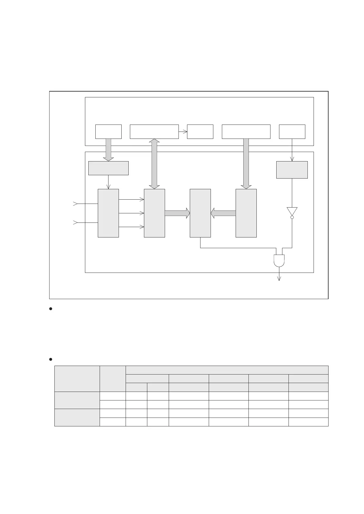
The figure below shows the configuration of HHSC:
※The structures of HHSC1 and HHSC2 are identical. The upper components in the
figure indicate the corresponding components of HHSC1, and the components in
brackets represent the corresponding components of HHSC2.
Up count
Down
count
Active
Mode select circuit
Present value register
Comparator
Set value register
Interrupt
prohibition
flag
Mode
select register
Values are equal
PLC special registers and special relays (in the memory of CPU)
D9231、D9230
(D9233、D9232)
D9224
(D9225)
M9196
(M9197)
D9227、D9226
(D9229、D9228)
M9062
(M9063)
HHSC
mode select register
HHSC
present value register
HHSC
counting direction flag
HHSC
set value register
HHSC
interrupt prohibit flag
X0
(X3)
X1
(X4)
Hardware circuit of the HHSC
Interrupt of HHSC1
(HHSC2)
From the figure above, HHSC possesses both CPU's memory registers and hardware circuit registers.
When executing the END instruction, the PLC system program automatically writes the HHSC's mode register, set
value register and interrupt prohibit flag to the hardware circuit. That also reads the HHSC's present value from the
hardware circuit and stores it in the CPU's present value register.
In order to meet the needs of fast and prompt process, the VS PLCs are also designed with the “Hardware high-speed
counter data move, HHCMV (FNC 189)” instruction. With the HHCMV instruction, the present value in the HHSC
hardware circuit can be read out immediately or the set value can be written to the HHSC hardware circuit.
Table of HHSC Working Modes:
HHSC No.
Input
Point
HHSC Operating Mode
1-Phase 2-Phase AB-Phase ×1 AB-Phase × 2
AB-Phase × 4
HHSC1
HHSC2
X0
X1
X3
X4
1 2
U
U
U/D
DIR
U/D
DIR
6
A
B
A
B
5
A
B
A
B
4
A
B
A
B
3
U
D
U
D
58
2-15-4 Hardware High Speed Counter
U: Up Counter Input D: Down Counter Input A: A-Phase Counter Input B: B-Phase Counter Input
U/D: Up/Down Counter Pulse Input DIR: Up/Down Directional Selector Input