The tables below list the special relays and registers related to the HHSCs:
■
Represents that component is read only.
M9062
M9063
■
M9196
■
M9197
D9224
D9227
D9225
D9228
D9226
D9229
D9230
D9231
D9232
D9233
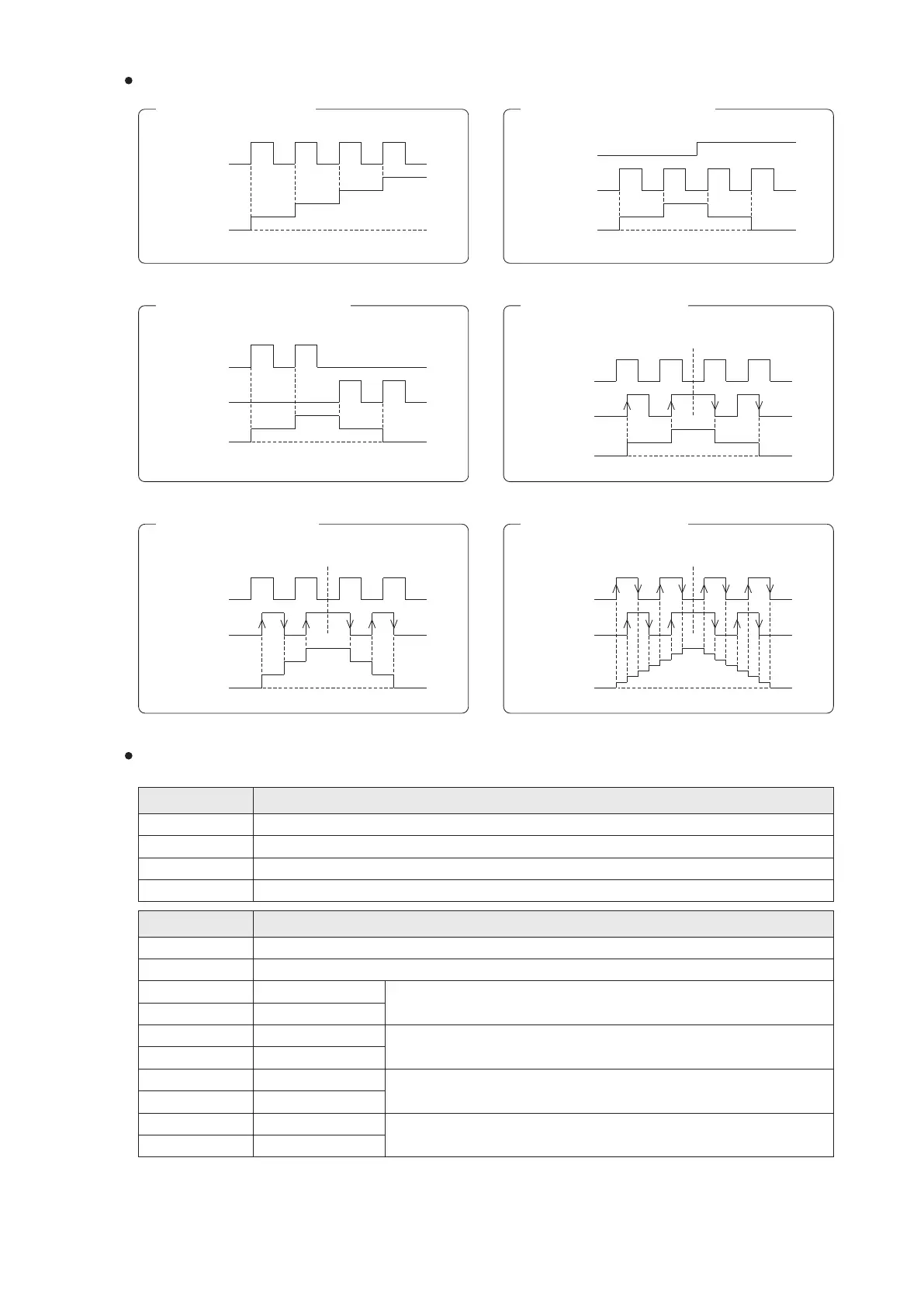
The operating modes of HHSC are illustrated by using the HHSC1.
Mode 1: 1-phase Up count
Mode 2: 1-phase Up/Down count
Mode 3: 2-phase Up/Down count
Mode 4: AB-phase×1 count
Mode 5: AB-phase×2 count Mode 6: AB-phase×4 count
DIR(X1)
U/D(X0)
U(X0)
HHSC1
Present value
U(X0)
D(X1)
The encoder is reversed here
59
The encoder is reversed here
HHSC1
Present value
HHSC1
Present value
A(X0)
B(X1)
HHSC1
Present value
A(X0)
B(X1)
HHSC1
Present value
The encoder is reversed here
A(X0)
B(X1)
HHSC1
Present value
To prevent the HHSC1's interrupt. Hardware High Speed Counter interrupt IHHC1 is prohibited.
To prevent the HHSC2's interrupt. Hardware High Speed Counter interrupt IHHC2 is prohibited.
HHSC1's counting direction ag. When M9196=“OFF”, up counting; when “ON”, down counting.
HHSC2's counting direction ag. When M9197=“OFF”, up counting; when “ON”, down counting.
HHSC1 counting mode selection. “0” is to disable the HHSC1; “1” ~ “6” represent different modes.
Lower 16 bits
Upper 16 bits
Lower 16 bits
Lower 16 bits
Lower 16 bits
Upper 16 bits
Upper 16 bits
Upper 16 bits
HHSC2 counting mode selection. “0” is to disable the HHSC2; “1” ~ “6” represent different modes.
The present value of HHSC1.
The present value of HHSC2.
The set value of HHSC1.
The set value of HHSC2.
Register ID No.
Description
Relay ID No.
Description
Up count
Down count