4-1-3 State and Action of SFC
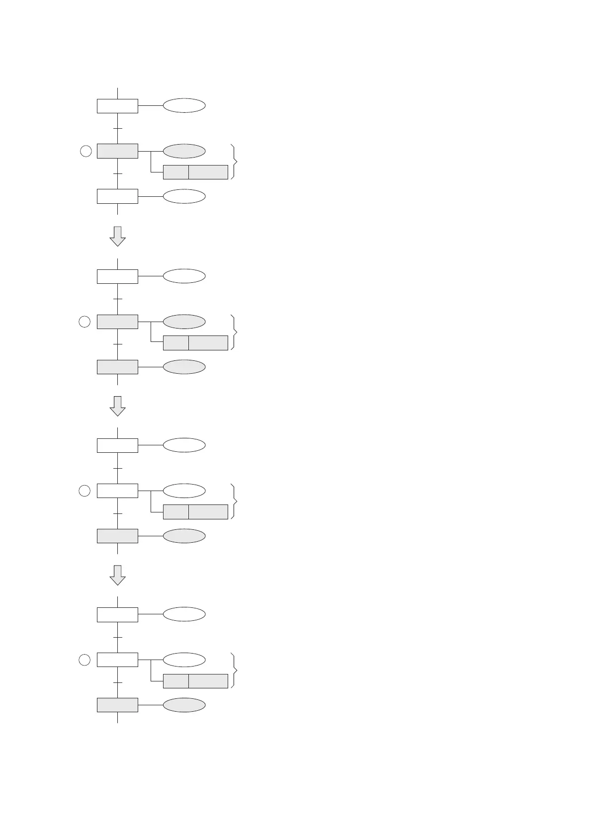
The VS series PLC uses step relay to indicate the state in the SFC. The diagrams below show the action of step relays
under various of situations.
S21=ON, the step is active, Y0=ON, Y1=ON.
S21
X1
S20=OFF, the step is not active, Y7=OFF.
S20
Y7
Y0
SET
Y1
S22
X0
Y2
S22=OFF, the step is not active, Y2=OFF.
S21=ON, the step is still active, Y0=ON, Y1=ON.
S22=ON, the step is active, Y2=ON.
At the next scan time, the step S21 turns from ON to OFF (inactive), but S21 is still executed.
S20=OFF, the step is not active, Y7=OFF.
S21=OFF, the step is executed but inactive, Y0 turns OFF;
Y1=ON because it was driven by the SET instruction.
S22=ON, the step is active, Y2=ON.
Then the next scan time, the step S21 will not be executed.
S20=OFF, the step is not active, Y7=OFF.
S21=OFF, the step is not executed, Y0=OFF;
Y1=ON because it was driven by the SET instruction.
S22=ON, the step is active, Y2=ON.
S21
X1
S20=OFF, the step is not active, Y7=OFF.
S20
Y7
Y0
SET
Y1
S22
X0
Y2
At the moment X0=OFF → ON, the active step will be transferred from the S21 to S22. The relay S22 truns
from OFF to ON, but S21 remains ON temporary.
1
2
3
S21
X1
S20
Y7
Y0
SET
Y1
S22
X0
Y2
S21
X1
S20
Y7
Y0
SET
Y1
S22
X0
Y2
4
92