M9076
M9077
M9078
M9079
M9080
M9081
M9082
M9083
■
M9075
D9075
D9074
D9077
D9076
D9079
D9078
D9081
D9080
D9083
D9082
D9085
D9084
D9087
D9086
D9089
D9088
D9091
D9090
D9093
D9092
D9095
D9094
D9097
D9096
56
2-15-3 Pulse Measurement
With the pulse measurement function, the VS series PLC can measure X0, X1, X3, X4 input pulse signal's ON width or
cycle period.
The pulse measurement function uses an 1/6 µs loop counter to store the count value to the specic special registers at
the rising edge and falling edge of the input signal respectively. And then calculate the pulse width or pulse period of
the input signal according to the contents of the registers. The calculated width or cycle is stored in the corresponding
special registers in the unit of 10 µs.
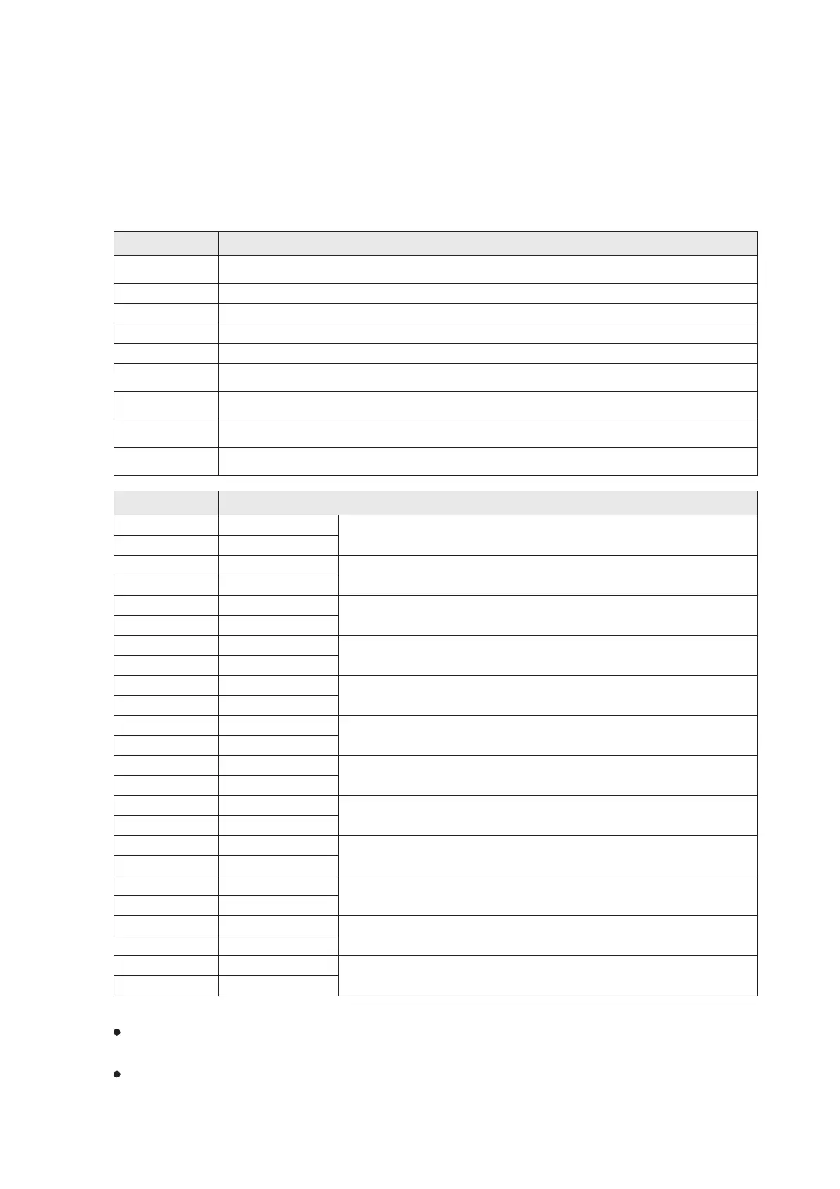
The tables below list the special relays and registers related to this function:
■
Represents that component is read only.
Register ID No.
Description
Relay ID No.
Description
To set the mode of X4's pulse measurement. “OFF”: pulse width measurement,
“ON”: pulse period measurement
Pulse measurement setting-up ag. Use this ag contact to active the pulse width / period measurement
function at the X0, X1, X3 or X4.
To start the X0 for pulse measurement.
To start the X1 for pulse measurement.
To start the X3 for pulse measurement.
To start the X4 for pulse measurement.
To set the mode of X0's pulse measurement. “OFF”: pulse width measurement,
“ON”: pulse period measurement
To set the mode of X1's pulse measurement. “OFF”: pulse width measurement,
“ON”: pulse period measurement
To set the mode of X3's pulse measurement. “OFF”: pulse width measurement,
“ON”: pulse period measurement
The X0's rising edge to catch the present value of loop counter. (unit: 1/6 µs)
The X1's rising edge to catch the present value of loop counter. (unit: 1/6 µs)
The X3's rising edge to catch the present value of loop counter. (unit: 1/6 µs)
The X4's rising edge to catch the present value of loop counter. (unit: 1/6 µs)
The X0's falling edge to catch the present value of loop counter. (unit: 1/6 µs)
The X1's falling edge to catch the present value of loop counter. (unit: 1/6 µs)
The X3's falling edge to catch the present value of loop counter. (unit: 1/6 µs)
The X4's falling edge to catch the present value of loop counter. (unit: 1/6 µs)
The X0's Pulse Width/Period Measurement cached value. (unit: 10µs).
The measurable range of Width: 10µs~100s, minimum Pulse Period: 20µs
The X1's Pulse Width/Period Measurement cached value. (unit: 10µs).
The measurable range of Width: 10µs~100s, minimum Pulse Period: 20µs
The X3's Pulse Width/Period Measurement cached value. (unit: 10µs).
The measurable range of Width: 10µs~100s, minimum Pulse Period: 20µs
The X4's Pulse Width/Period Measurement cached value. (unit: 10µs).
The measurable range of Width: 10µs~100s, minimum Pulse Period: 20µs
Lower 16 bits
Lower 16 bits
Lower 16 bits
Lower 16 bits
Lower 16 bits
Lower 16 bits
Lower 16 bits
Lower 16 bits
Lower 16 bits
Lower 16 bits
Lower 16 bits
Lower 16 bits
Upper 16 bits
Upper 16 bits
Upper 16 bits
Upper 16 bits
Upper 16 bits
Upper 16 bits
Upper 16 bits
Upper 16 bits
Upper 16 bits
Upper 16 bits
Upper 16 bits
Upper 16 bits
Must use the M9075 to drive M9076~M9079 to activate the pulse measurement function at the corresponding input
point X0, X1, X3 or X4.
The pulse measurement and external interrupt functions can use an external input point at the same time.
 Loading...