VS Series PLCs read the ON/OFF status of various external switches and sensing elements as operating conditions
through the input points. To prevent problems such as noise interference and switch bouncing, there is a filter of about
10ms equipped at each input point. Since the external input X0~X7 of a Main unit are designated as multi-function input
points to perform various high speed functions, therefore, the filter time of these 8 input points is adjustable.
Functions of these 8 output points are listed below.
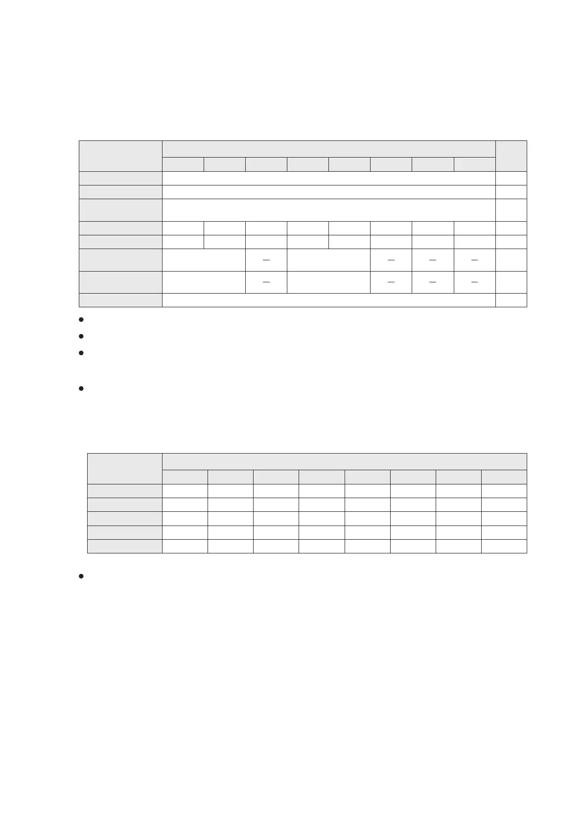
2-2 External Input (X) and External Output (Y)
2-2-1 External Input (X)
Ref.
Page
For the descriptions of each item, please refer to the page listed at the “Ref. Page ” above.
The contact of a common input point in the program is available to work with an other special function.
When one of the X0~X7 performs a mentioned special function above, this input point is not reusable with another
special function. However, the External Interrupt could cooperate with Pulse Measurement function. (For details,
please see the specific function description.)
When a multi-function input point is performing a special function, the response of the point requires fast and
relatively sensitive (the fast reaction, the more sensitive), contrarily susceptible to noise interference.Therefore, pay
special attention to its external wiring, try to avoid interfering sources, and use isolation lines.
Software High
Speed Counter
Function
Hardware High
Speed Counter
IX3P/F
External Input Point
X0
X1 X2
X3
X4
X5 X6
X7
Common Input
External Interrupt
Pulse Capture
Pulse Measurement
Use D9020 to adjust the lter time as 0~60ms
Use the SPD instruction to perform the speed detection function
Use C235~C255 1-phase/2-phase/AB phase counters, besides to generate IHC0~IHC7 interrupt
IX0P/F IX1P/F IX2P/F IX4P/F IX5P/F IX6P/F IX7P/F
M9170 M9171 M9172 M9173 M9174 M9175 M9176 M9177
HHSC1, to make
the IHHC1 interrupt
HHSC2, to make
the IHHC2 interrupt
Width / Period
measurement
Can be the input points of the positioning control's DOG, PG0, INT signals or for the handwheel.
179
186
25
54
55
58
56
423
When a mentioned special function above performs, the filter time of this input point will be automatically adjusted to
0ms (deviates form D9020). To prevent noise interference, input points X0~X7 are also equipped with RC filters.
Thus, the filter time of 0 ms is not true 0 ms. In addition, the response time of input points X0~X7 is varied depending
on the Series of VS1, VS2, VSM or VS3.
When filter time is adjusted as 0ms, the minimum pulse width required to transmit input signals to respective input
points are listed as follows.
X0
X1 X2
X3
X4
X5 X6
X7
VS1
VS2
VSM
VS3
Series
50µs
10µs 10µs 10µs 10µs 10µs 10µs 10µs 10µs
2.5µs 2.5µs 2.5µs2.5µs
50µs 50µs
10µs
50µs 50µs 50µs 50µs 50µs
10µs 10µs 10µs
2.5µs 2.5µs 2.5µs2.5µs 10µs 10µs 10µs 10µs
0.5µs 0.5µs 0.5µs0.5µs 10µs
VSM-28ML
10µs 10µs 10µs
14
Frequency Meter
Positioning Control
Width / Period
measurement
External Input Point