468
Stepper motor drive
Pulse output Y0
Direction output Y1
VS1-32MT
Stepper
motor
X16
X2X17
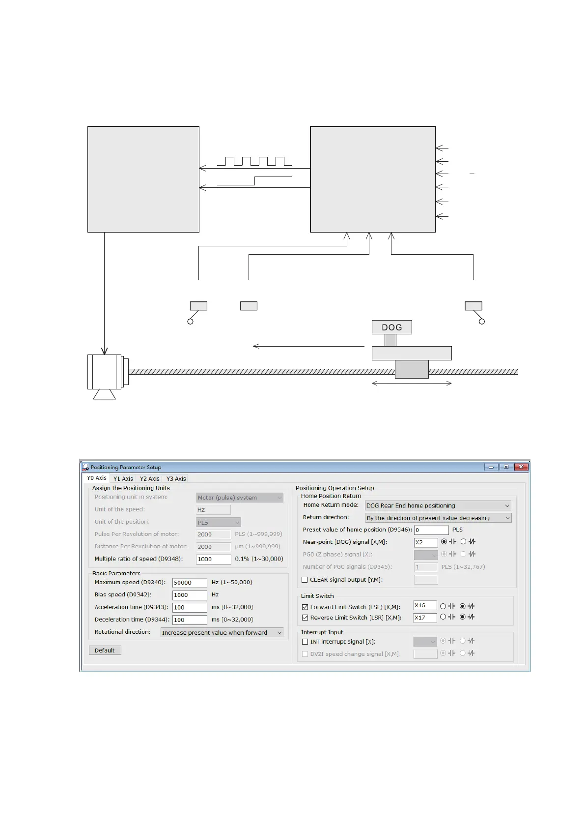
Use the “Positioning Parameter Setup” function which is provided by the programming tools Ladder Master S to set the
relevant parameters about the Y0 axis. Select the “DOG Rear End home positioning” as the home return mode.
Then the settings will be written onto the PLC with the project.
Home position return
Move back to zero point
Single-speed positioning
Stop
JOG+
JOG
X14
X15
X12
X13
X11
X10
CK
DIR
8-4 Positioning Program Example
8-4-1 Positioning Program Example for the VS1 or VS2 Series PLC
This example uses the combination of the VS1 or VS2 transistor Main Unit and a stepper motor drive to complete a
positioning control system. This control example carries out the home position return, forward JOG, reverse JOG and
single-speed positioning functions. The brief diagram of the system is shown below.
LSR
Reverse limit
switch
DOG
Near point
signal
LSF
Forward limit
switch
Direction of home positioning
Sliding table
Driving screw