4-4 Precautions About the Composition of the SFC
To create an user program for the VS PLC, the Ladder Master S provides the SFC to combine with the original ladder
diagram. Be sure to understand its specications and restrictions, in order to use it smoothly and complete the control
program correctly.
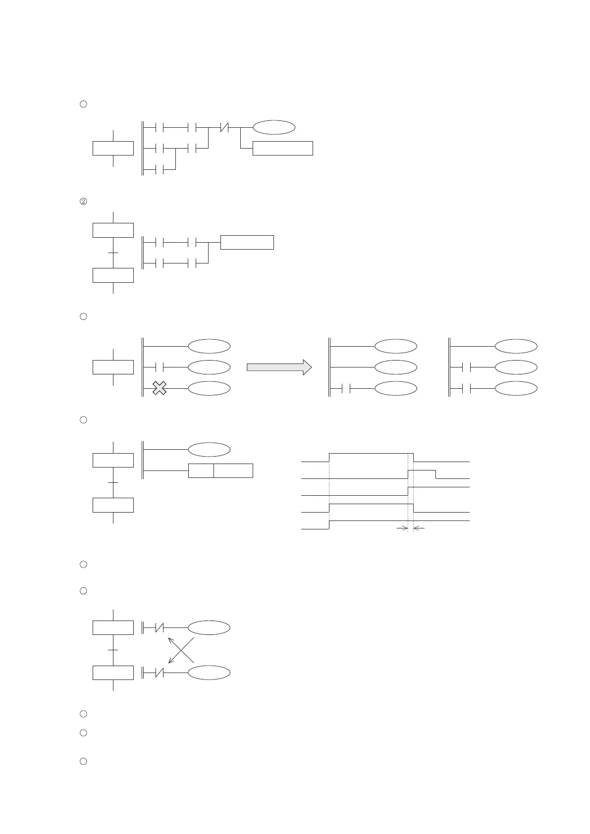
The control process within a step can use a variety of serial / parallel links, outputs and application instructions.
1
S10
X0 M10 T0
M100X20
Y5
T0
K50
MOV D0 D 1
The transfer condition between two steps can be driven by serial / parallel links.
T0 X0
X1T1
TRA N S1 0
S105
S10
3
The control outputs in a step may directly drive by the inner bus line. However, once a contact is inserted, the
subsequent outputs and application instructions cannot directly drive from the bus line.
S10
T2
Y1
Y2
Y0
Should be modied as
T2
Y0
Y1
Y2
T2
M9000
Y0
Y1
Y2
or
When using the OUT instruction to drive a coil in the step, the coil will turn OFF after the effective state transferred.
When using the SET instruction to drive a coil ON in the step, the coil will retain ON after the effective state transferred.
4
S10
S11
X0
Y0
SET
Y1
When the effective state is transferring between two sequential steps, both of the states are ON at this scan time.
Please refer to the above gure.
5
Since both the states of two sequential steps will ON at the scan time of transferring. It is necessary to add the output
interlock circuits.
6
S10
S11
Y1
Y0
Y0
Y1
Motor rotates forward.
Motor rotates backward.
Interlock
S10
X0
S11
Y0
Y1
A SFC cannot be written in a subroutine.
Although the use of the jump (CJ) instruction is not prohibit inside of a SFC step, it makes the program process more
complicated and should be avoided.
7
8
When there is a SFC in the PLC program, do not use the SET or OUT instruction in the interrupt subroutine to drive
the step relay.
9
99
One Scan Time