74
BFM No.
#0
#1
#2
#3
#4
Component Description
To assign the analog input modes of AI1~AI4. When the power is turned from OFF to ON, the default value is H0000.
When the power is turned from OFF to ON, the default value is 10.
The available range is 1~32,767, otherwise it is equivalent to 10.
#5
#6
#7
#8
#20
#23
#30
#31
Identication code: VS-6A = K204 (can use the FROM instruction to check whether the place is this module or not)
The version number of this module. (the content value XX indicates Ver. X.X)
Converted digital value of AI1 (the average times is designated by BFM #1).
Converted digital value of AI2 (the average times is designated by BFM #2).
Converted digital value of AI3 (the average times is designated by BFM #3).
Converted digital value of AI4 (the average times is designated by BFM #4).
To assign the analog output modes of AO1~AO2. When the power is turned from OFF to ON, the default value is H00.
To assign the holding modes of AO1~AO2. When the power is turned from OFF to ON, the default value is H00.
To set the average times of AI2.
To set the average times of AI3.
To set the average times of AI4.
To set the average times of AI1.
#21
#21
When the power is turned from OFF to ON, the default value is 0.
The digital set value of AO1.
The digital set value of AO2.
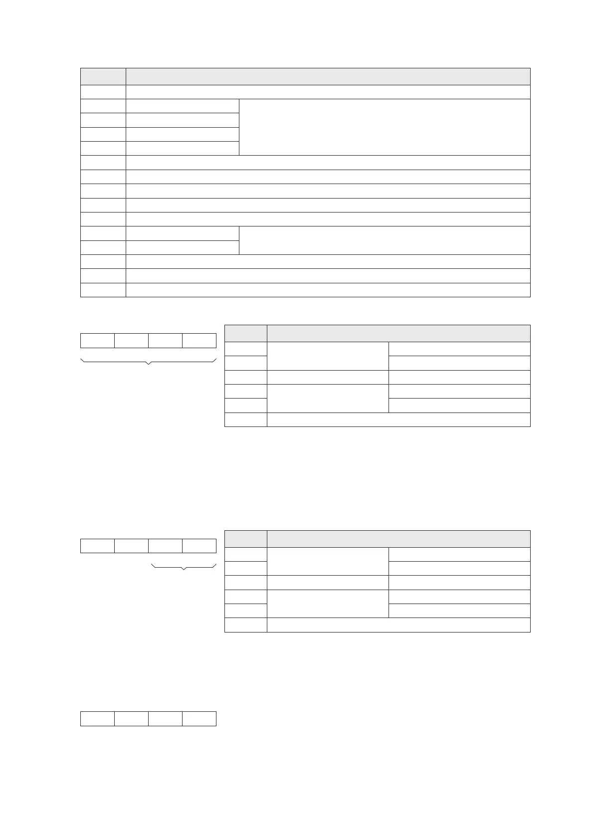
BFM#0 To appoint the modes of analog inputs: (the sliding switch should also consistent with the modes)
Example: If the BFM #0 of a VS-6A is set to be H5420, then
AI1: For –10V~+10V voltage input, that will be converted to the value –32,000~+32,000 at this mode.
AI2: For 4mA~20mA current input, that will be converted to the value 0~+16,000 at this mode.
Value of
Nibble
0
1
2
3
4
Other
Disabled
–20mA~+20mA current input
–10V~+10V voltage input
4mA~20mA current input
Analog Input Mode
Converted digital value:–32000~+32000
Converted digital value:–10000~+10000
Converted digital value:0~+16000
Converted digital value:–16000~+16000
Converted digital value:–20000~+20000
b15 b0BFM#0
BFM#23 To appoint the output holding mode: (for the PLC status turns from RUN to STOP)
b15 b0
AO1
BFM#23
If the value in the nibble = 0, the channel will keep the last output, even PLC
is STOP.
If the value in the nibble ≠ 0, the channel will change its digital set value = 0
at STOP.
BFM#20 To appoint the mode of analog output:
Example: If the BFM #20 of a VS-6A is set to be H20, then
AO1: For -10V~+10V voltage output, that will use the digital set value -32,000~+32,000 at this mode.
Value of
Nibble
0
1
2
3
4
Other
Disabled
–20mA~+20mA current output
–10V~+10V voltage output
4mA~20mA current output
Analog Output Mode
Digital set value: –32000~+32000
Digital set value: –10000~+10000
Digital set value: 0~+32000
Digital set value: –32000~+32000
Digital set value: –20000~+20000
b15 b0BFM#20
Nibble #4
Nibble #3
Nibble #2 Nibble #1
NullNull
To assign input modes
AI2 AI1AI4 AI3
Nibble #4
Nibble #3
Nibble #2 Nibble #1
AI3: For -20mA~+20mA current input, that will be converted to the value -32,000~+32,000 at this mode.
AI4: Disabled
Null
To assign
output modes
AO2 AO1Null
Nibble #4
Nibble #3
Nibble #2 Nibble #1
AO2: For 4mA~20mA current output, that will use the digital set value 0~+32,000 at this mode.
AO2
2-17-4 Buffer Memory BFM in the VS-6A Module