417
The VS series PLC's positioning control functions are achieved by the positioning instructions, parameters (by the
Ladder Master S to congure) and relevant special devices, the following sections will introduce those respectively.
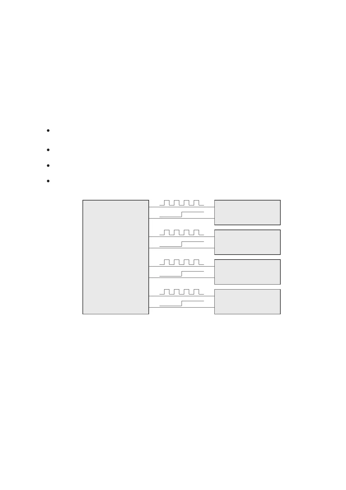
The VS series PLC
Servo motor driver or
step motor driver
Y1
Y2
Y3
CK
CK
CK
CK
DIR
DIR
DIR
DIR
Y0
Y4
Y5
Y6
Y7
8. Statement of Positioning Control Functions
The VS series PLC Main Unit provided with four high-speed pulse output points, and thus can operate four axis controls.
In the multi-axis positioning control applications, it is very suitable and effective.
The pulse output frequency of the VS1 and VS2 Series transistor PLCs can reach up to 50 kHz, can be used to complete
various of basic positioning control.
The VSM Motion Control Main Unit is equipped with quick reaction high-speed I/O points, because it is special design
for positioning control applications with complete positioning functions.
The VS3 High Performance Main Unit can satisfy the most diverse and the highest level of applications, the transistor
model also possesses complete positioning control functions.
The pulse output frequency of the VSM and VS3 Series PLCs can reach to 200 kHz, furthermore the VSM-28L can even
reach to 1 MHz. All the VS series PLC can support 17 positioning instructions of complete functions and thus can
complete various types of exquisite and smooth positioning control.
When using the positioning control functions of the VS series PLC Main Units, some common precautions are noted
below:
The VS1 and VS2 series transistor models are provided with four 50 kHz high-speed pulse outputs, the VSM and VS3
transistor models are provided with four 200 kHz high-speed pulse outputs. Moreover, the VSM-28L provides four
1 MHz high-speed line-driver output circuits.
There is no limitation on the number of times that positioning instructions are wrote at the user program. However,
must regard to that do not use two or more instructions to drive the same output point at the same time.
The load voltage of transistor output points is DC5V~24V, and for the general output uses the current capacity is
0~0.5 A; but when a point Y0~Y3 is assigned for the high-speed pulse function, its current is 0~100 mA.
About the positioning control method at the VS series PLC, its controlling output form is “Pulse train + Direction
signal”. The output points for the direction signals can use Y0~Y7 or internal auxiliary relays M.
Nonetheless, those are better using Y0~Y7 to minimize output delay.
Servo motor driver or
step motor driver
Servo motor driver or
step motor driver
Servo motor driver or
step motor driver