67
EC Card Register (Simple Code) Related to the VS-3ISC-EC
EC3
EC1 EC2
EC1D0
EC1D1
EC1D2
EC1D3
EC1D4
EC1D5
EC1D6
EC1D7
EC1D8
EC2D0
EC2D1
EC2D2
EC2D3
EC2D4
EC2D5
EC2D6
EC2D7
EC2D8
EC3D0
EC3D1
EC3D2
EC3D3
EC3D4
EC3D5
EC3D6
EC3D7
EC3D8
VO set value of CH2 ,0~1000
EC1D18
EC1D19
Identication code: K104 (If code = K240, means connecting error between Main Unit and card)
The version number of this card. (the content value XX indicates Ver. X.X)
EC2D18 EC3D18
EC2D19 EC3D19
VO set value of CH1, 0~1000
VO set value of CH3 , 0~1000
V+ measured voltage value of CH1.
V+ measured voltage value of CH2.
V+ measured voltage value of CH3.
VO Max. of CH1.
VO Max. of CH2.
VO Max. of CH3.
The output ratio at the VO terminal that connect to the
analog speed control point of inverter.
This VO set value is the percentage of 0 to “VO Max.”
If the set value <0, the output ratio = 0 (0 %).
If the set value >1000, the output ratio= 1000 (100.0 %).
Measure the external control use power from inverter by a
voltage meter and ll in the result value here. If the result is
10V, then ll in 1000 (by unit of 0.01V). If the lled result is
not between 400 and 1200, then the VO point will output 0V.
Fill in the control input voltage of the maximum speed for
the inverter. If its effective range is 0~10V, then ll in 1000
(by unit of 0.01V). If the lled value is not in the range
between 0 to “V+ measured voltage”, then the VO point will
output 0V.
Component Description
EC Card Register (Simple Code) Related to the VS-2TC-EC
EC3
EC1 EC2
EC1D0
EC1D1
EC1D2
EC1D3
EC1D6
EC1D7
EC1D17
EC2D0
EC2D1
EC2D2
EC2D3
EC2D6
EC2D7
EC2D17
EC3D0
EC3D1
EC3D2
EC3D3
EC3D6
EC3D7
EC3D17
EC1D18
EC1D19
EC2D18 EC3D18
EC2D19 EC3D19
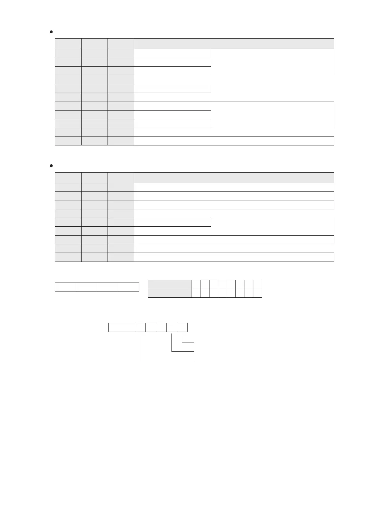
Assign Thermocouple Type:
b15 b0
TC2 TC1
Example: If a VS-2TC-EC is installed at the EC1, and its EC1D0 is set to be H0010, then
TC1: K Type of thermocouple input, TC2: J Type thermocouple input.
Value of Nibble
Thermocouple Type
0
1
2
3 4
5
6
J
K R
S
T E B
7
N
Status and Error Flag:
If Value of Nibble is not 0~7,
the channel is disabled.
b0
b1b2
b3
b4
b15~b5
TC1 disconnected or converted value exceeds the range
TC2 disconnected or converted value exceeds the range
The hardware error ag of this card
Component Description
Usable set value is 1~32767; other values =5.
The version number of this card. (the content value XX indicates Ver. X.X)
To assign the thermocouple types for TC1~TC2.
Converted temperature value of TC1, with unit as 0.1 ℃ or 0.1 ℉.
Converted temperature value of TC2, with unit as 0.1 ℃ or 0.1 ℉.
To set the average times of TC1
To set the average times of TC2
Status and error ag
Identication code: K105 (If code = K240, means connecting error between Main Unit and card)
Null Null
To assign the unit of temperature measurement. 0:℃; 1:℉; other values: ℃.
Nibble #4
Nibble #3
Nibble #2 Nibble #1